


(2)
Thank you for purchasing the Dayton Audio
®
MA1240 Twelve Channel Multi-Zone Amplifier. The versatility of the
MA1240 makes it the perfect choice for almost every type of custom multi-room audio system. Its tabletop or rack-
mountable design allows it to be integrated easily into high-end whole house audio systems.
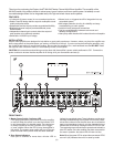
INSTALLATION:
Dayton Audio amplifiers are designed to help deliver a great audio experience. However, where you place the amplifier can
have a large effect on the performance you receive, and the life of the unit. If you are not rack-mounting the amplifier, posi-
tion it with all feet resting on a solid level surface. Be sure that the amplifier is in a well-ventilated area and DO NOT install
the amplifier near a source of heat or in an extremely humid or wet location.
CAUTION: All connections and switching must be done with the amplifier’s power switch positioned to ‘Off’. Connect the
power cord last to be sure that the amplifier is off during all of your connections and set up.
FEATURES:
• 12 channels (6 stereo zones) in one convenient enclosure
• Stable Class AB design delivers superior audiophile sound
quality and performance
• Independent and bus inputs provides unparalleled exibility
• Bridgeable channel outputs provide additional power
when needed
• Independent channel gain controls allow the output of
each speaker to be perfectly matched
• Switchable 115/230V input voltage
• Manual, auto, or triggered on/off for integration into any
automated system
• Multi-stage protection circuitry for reliability and easy
troubleshooting of audio system
• Installer-friendly setup and connections
• Can be converted easily between rack-mount and
tabletop configurations
• Heavy-duty steel chassis with brushed aluminum faceplate
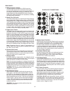
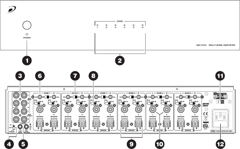
FRONT PANEL:
1. Master Power Switch / Indicator LED
Front panel pushbutton power switch turns the amplifier
on and off. When the switch is on and the indicator LED
is red, the amplifier is in standby mode. The remote turn
on switch (located on the rear) is either in the “trigger”
or “auto” position. When the LED is blue, the amplifier is
fully active. The master power switch will turn off the am-
plifier no matter which power mode has been selected.
2. Zone Status Indicators
Each pair of channels or zones has a bi-color LED to
indicate its operational status. These indicators provide quick
and easy troubleshooting of the system. If the circuitry deter-
mines that a channel must be shut down due to excessive
heat or low impedance (a short), only the channels that are
affected will be turned off causing the zone LED to turn red.
The remaining zones will continue to operate and maintain a
blue LED status. Once the condition has been corrected for
the zone in question, the status LED will return to blue.
Note: When the power LED is red and the zone status LEDS
are not lit (off) indicates the unit is in stand by mode.
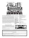
~115VAC 60Hz Fuse:T8AL
~230VAC 50Hz Fuse:T4AL