


page 19
Macro-Tech MA-24X6 & 36X12 Power Amplifiers
Operation Manual
Each channel is powered by its own power
transformer, T100 or T200. Both channels
share TF-1, a low voltage transformer. The sec-
ondary outputs of each transformer are full-
wave rectified by heavy duty bridge rectifiers
and are filtered by large computer grade capac-
itors. A thermal switch embedded in each
transformer protects them from overheating.
The low voltage transformer TF-1 uses a sepa-
rate fan motor winding. The TF-1 output is rec-
tified by diodes D1-4, generates an unregulated
24 volts. Monolithic regulators U1-2 provide a
regulated ±15 volts.
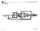
For simplicity, the following discussion of the
circuitry and operation will refer to one channel
only. Please refer to the block diagram in Figure
6.1
The input signal at the phone jack passes
directly into the balanced gain stage (U104-
C,D). Use of a PIP module for input signal
causes the input signal to pass through the PIP
and then to the balanced gain stage.
The balanced gain stage (U104-C,D) causes
balanced to single-ended conversion to take
place using a difference amplifier. From there,
gain can be controlled with a potentiometer.
The error amp (U104-A) amplifies the differ-
ence between the output signal and the input
signal from the gain pot, and drives the voltage
translator stage.
The voltage translator stage channels the signal
to the Last Voltage Amplifiers (LVAs), depend-
ing on the signal polarity, from the error amp
U104-A. The +LVA (Q105,Q125) and the –LVA
(Q110,Q126), with their push-pull effect
through the bias servo Q318, drive the fully
complementary output stage.
The bias servo Q318 is thermally coupled to
the heat sink, and sets the quiescent bias cur-
rent in the output stage to lower the distortion
in the crossover region of the output signal.
D301, D302, D303, and D304 are used to
remove the charge on the unused portion of the
output stage, depending on the polarity of the
output signal.
With the voltage swing provided by the LVAs,
the signal then gains current amplification
through the Darlington emitter-follower output
stage.
The bridge-balanced circuit (U104-B) receives
a signal from the output of the amplifier, and
differences it with the signal at the Vcc supply.
The bridge-balanced circuit then develops a
voltage to drive the bridge-balanced output
stage. This results in the Vcc supply having
exactly one half of the output voltage added to
their quiescent voltage. D309, D310, D311 and
a trimmer resistor set the quiescent current
point for the bridge-balanced output stage.
The protection mechanisms that affect the sig-
nal path are implemented to protect the ampli-
fier under real-world conditions. These
conditions are high instantaneous current,
excessive temperature, and operation of the
output devices outside safe conditions.
Q107 and Q108 act as a conventional current
limiter, sensing current in the output stage. The
allowable current level is also adjusted as a
function of voltage. When current at any one
instant exceeds the design criteria, the limiters
remove the drive from the LVAs, thus limiting
current in the output stage to a safe level.
To further protect the output stages, a specially
developed ODEP (Output Device Emulation
Protection) circuit is used. It produces an ana-
log output proportional to the always changing
safe operating area of the output transistors.
This output controls the translator stage by
removing any drive that exceeds the safe oper-
ating area of the output devices. Thermal sen-
sor S100 gives the ODEP circuits vital
information on the operating temperature of the
heatsink on which the output devices are
mounted.
Should the amplifier fail in such a way that
would cause DC across the output lead, the DC
protection circuit senses this on the negative
feedback loop and shuts down the power sup-
ply until the DC is removed.
6 Theory of Operation