D Series Power Amplifiers
page 8
Operation Manual
2.6 Wire Your System
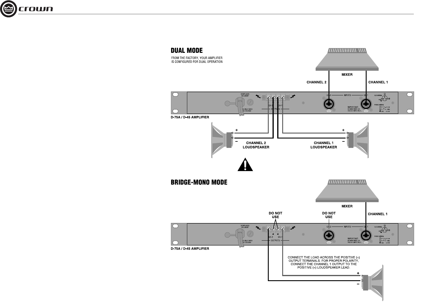
2.6.1 Dual Mode
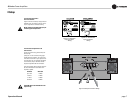
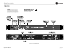
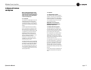
Typical input and output wiring is shown in Figure 2.6.
INPUTS: Connect input wiring for each channel.
OUTPUTS: Maintain proper polarity (+/-) on output connec-
tors.
Connect Channel 1 positive (+) speaker load to Channel 1
positive terminal of amp; repeat for negative (-). Repeat each
channel wiring as for Channel 1. Refer to Section 2.5 for out-
put connector pin assignments.
2.6.2 Bridge-Mono Mode
Your amplifier is factory-configured for dual (stereo) opera-
tion. As an option, the unit can be configured for higher
power, single-channel, bridge-mono mode by an authorized
Crown Service Center. To prevent damage to the
amplifier, do not operate the unit in bridge-mono
mode without the Service Center modification.
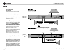
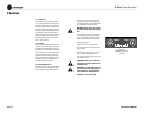
Typical input and output wiring is shown in Figure 2.7.
INPUTS: Connect input wiring only to CH 1.
OUTPUTS: Connect the speaker across the positive output
terminals. Do not use the negative terminals when the ampli-
fier is being operated in Bridge-Mono mode.
NOTE: Crown provides a reference of wiring pin assign-
ments for commonly used connector types in the Crown
Amplifier Application Guide available at www.crownau-
dio.com.
NOTE: When operating in Bridge-Mono mode, turn
down (full CCW) the CH 2 level control. The CH 1
level control works both channels.
If your loudspeakers don’t need the additional volt-
age, and you only have one input signal to drive mul-
tiple loudspeakers, you can use bridge-mono mode
without actually bridging the outputs. Bridge-mono
mode is like dual mode except the channel 1 input
feeds both outputs, and the channel 2 output is
inverted. To use bridge-mono mode without bridging
the outputs, wire your loudspeakers as you would for
dual mode, but invert the polarity of the channel 2
output wiring (positive goes to negative, and negative
goes to positive).
2 Setup
Do not wire the amplifier in bridge-mono
mode without having it modified by an
authorized Crown Service Center.
Figure 2.6
System Wiring
for Dual Mode
Figure 2.7
System Wiring
for Bridge-Mono
Mode


