D Series Power Amplifiers
page 12
Operation Manual
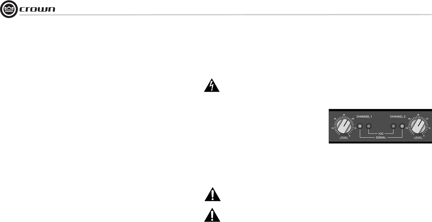
3.3 Indicators
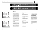
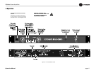
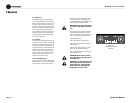
Your amplifier has five front panel indicators.
First, a power indicator behind the front panel
becomes visible when the unit is turned on and
has power. A signal indicator for each channel
(Figure 3.2 ) flashes when there is output from
the amplifier. The IOC (Input/Output Compara-
tor) indicators work like sensitive distortion
meters and flash when the amplifier causes any
distortion of 0.05% or more. The IOC indica-
tors typically glow for about one minute after
the AC power is turned off.
3.4 Controls
A power switch and detented level controls are
located on the front panel. When you power up
the amplifier, remember that the unit does not
have a turn-on delay. Each channel has its own
level control which is used to adjust the desired
output level. Both level controls (Figure 3.2)
are used in dual mode, but only the channel 1
control should be used in bridge-mono mode.
Channel 2 control should be fully counter-
clockwise in bridge-mono mode.
3.5 Fuse Replacement
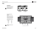
The AC mains fuse is located on the back panel
beside the power cord. This fuse will not blow
unless something is wrong. Before replacing
the unit’s fuse, you should be sure to fix the
source of the problem. If the problem is not
immediately apparent, the unit probably needs
to be serviced by a qualified technician.
WARNING: Always unplug the amplifier
from the AC mains before removing the
fuse.
To replace the fuse, turn off the power switch
and disconnect the power plug from the AC
mains. Unscrew the fuse holder cap (shown in
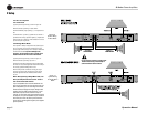
Figure 3.1, back view) and remove the fuse.
Install appropriate fuse:
100 or 120 volt mains: 2 Amp type 3AG.
North American 200, 220 and 240 volt mains: 1
Amp type 3AG.
European 220 or 240 volt mains: 1 Amp IEC
type T, time lag, low breaking capacity.
Then, simply resecure the fuse holder cap and
reconnect the AC mains.
IMPORTANT: Never install a fuse that
has a higher current rating than the rec-
ommended value.
IMPORTANT: The 3AG and IEC fuses are
different physical sizes and require dif-
ferent holder caps. The 3AG and IEC
fuses should not be exchanged even
though they are the same value.
.
Figure 3.2
Indicators and Level
Controls
3 Operation


