


CP660 Power Amplifi er
Operation Manualpage 8
3 Setup
3.6 Wire Your System
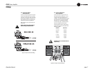
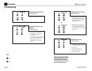
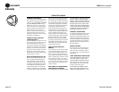
3.6.1 Stereo Mode
Typical input and output wiring is shown in
Figure 3.6.
INPUTS: Connect input wiring for each
channel. Maintain proper polarity (+/-) on
input connectors.
OUTPUTS: Maintain proper polarity (+/-) on
output connectors.
Connect Channel 1 positive (+) speaker load
to Channel 1 positive (red) terminal of amp;
repeat for negative (-). Repeat each channel
wiring as for Channel 1.
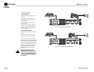
3.6.2 Bridge-Mono Mode
Typical input and output wiring is shown in
Figure 3.7.
INPUTS: Connect input wiring to lower-
numbered channel only for each channel
pair.
NOTE: Crown provides a reference of wiring
pin assignments for commonly used connector
types in the Crown Amplifi er Application Guide
(Section 1.21.) available at www.crownaudio.
OUTPUTS: Connect the speaker across the red
binding post of each channel pair. Do not use
the black binding posts of the channel pair
when the pair is being operated in Bridge-
Mono mode.
NOTE: Set the level control for the
higher-numbered channel of the chan-
nel pair to zero (0) when operating the
channel pair in Bridge-Mono mode, as
the lower-numbered level control works
both channels.
Figure 3.6. System Wiring, Stereo Mode
Figure 3.7. System Wiring, Bridge-Mono Mode