


page 17
CE Series Power Amplifiers
Operation Manual
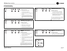
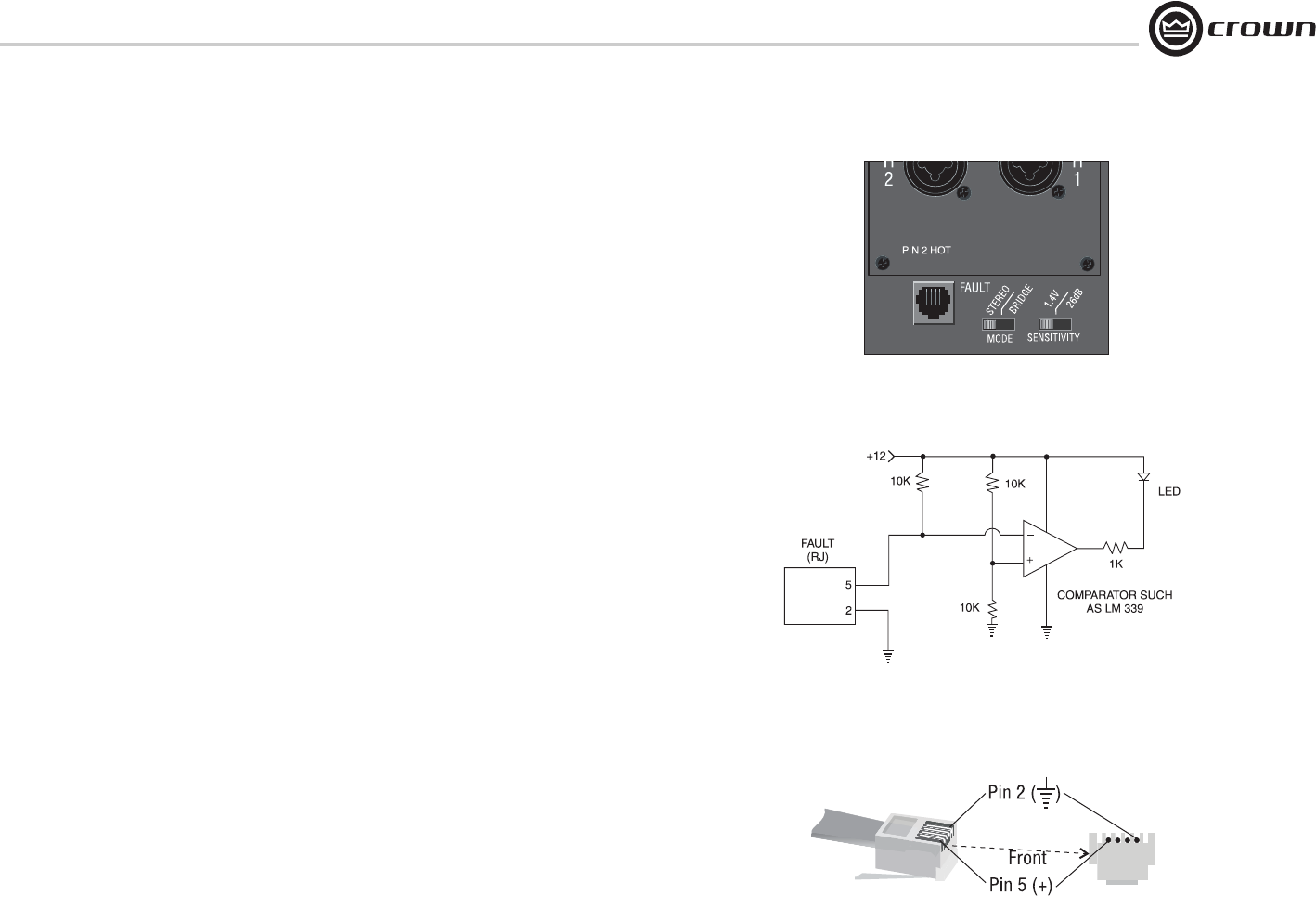
4.2.2 Fault Monitoring
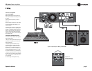
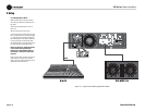
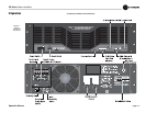
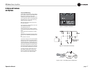
The Fault (RJ-11) jack, which looks like a telephone
jack, is located on the back of your CE Series ampli-
fier (Figure 4.3). It gives you an easy way to
remotely monitor the amplifier’s fault status. To set
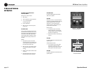
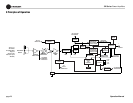
up a circuit that will cause an LED to light whenever
a fault status occurs, you can simply use the sug-
gested circuit shown in Figure 4.4.
When using this circuit, the LED will glow under
any of these conditions:
• The amplifier has just been turned on and is still
in the 4-second turn-on delay.
• The heatsinks are too hot.
•The transformer thermal protection is activated.
• The amplifier output wires have developed a short
circuit.
• The limiter has been overdriven by > 6 dB for a
long time.
• The amplifier output stage has stopped operating.
Refer the unit to an authorized Crown Service Cen-
ter.
• The amplifier is turned off.
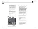
If you choose to design your own circuit to interface
this signal to your system, note that this RJ jack is
polarity sensitive. Pin 2 must be grounded, and Pin
5 must be supplied with a positive voltage pull-up
(positive with respect to ground). Refer to Figure 4.5
for RJ jack pin assignments. The maximum signal
that can be exposed to the Fault jack is 35VDC and
10 mA. Best results are obtained with 10 mA LEDs.
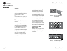
The mating connector for the CE Series TX RJ-11
jack contains 4 contact pins in a 6-slot case, as
shown. For additional information please contact
your local dealer or Crown Technical Support.
Figure 4.4 Fault Status LED Circuitry
Figure 4.5 RJ-11 Jack Wiring and Pin Assignments
4 Advanced Features
and Options
Figure 4.3 Location of Fault Jack