


XLS Series Power Amplifiers
page 15
Operation Manual
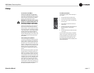
NOTE: For detailed information about
these Crown amplifier features, please
consult the Crown Amplifier Application
Guide, available on the Crown website
at www.crownaudio.com.
4.1 Protection Systems
Your Crown amplifier provides extensive pro-
tection and diagnostic capabilities, including
output current limiting, DC protection, circuit
breaker, and special thermal protection for the
unit’s transformers.
4.1.1 Output Current Limiting
Output Current Limiting circuitry protects the
amplifier output stage for damage caused by
short-circuit loads.
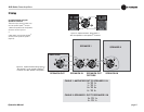
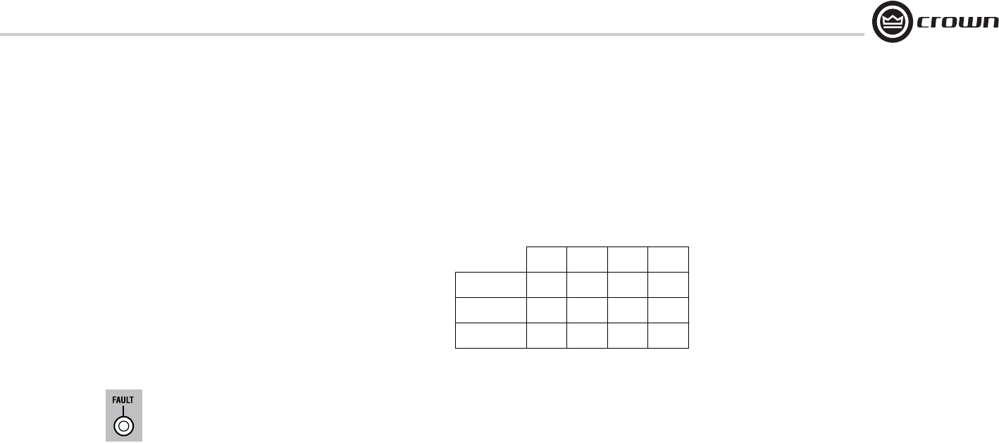
4.1.2 DC Protection
DC Protection disconnects the loudspeaker
load in the event of an output DC offset exceed-
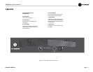
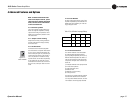
ing 2V. In such an event the yellow Fault LED
will illuminate (see Figure 4.1) and both ampli-
fier channels will be muted. In the majority of
cases, DC protection is indicative of a faulty
amplifier channel, and will be accompanied by
an illuminated Clip LED, even with no input
connected and level controls set at minimum. If
this is the case, contact your dealer or service
center.
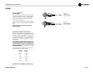
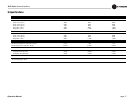
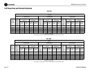
4.1.3 Circuit Breaker
The high-voltage power supplies of your Crown
amplifier are protected by a circuit breaker. The
breaker rating varies depending on model and
supply voltage as follows:
4.1.4 Thermal Protection
The Thermal Protection circuit will activate if
the internal heatsink temperature exceeds
proper operating temperatures (194 °F, 90 °C).
When the heatsink temperature has fallen to a
safe level, this protection circuit will automati-
cally be reset. Principle causes of thermal pro-
tection are:
1) Inadequate ventilation of the equipment rack
2) Incorrect load impedance
3) Output cable short circuit
4) Blocked air vent
5) Heatsinks in need of cleaning
6) Cooling fan failure.
The cause of your amplifier’s thermal protection
state should be determined and corrected as
soon as possible. Without correction, the Ther-
mal Protection circuit will typically reactivate.
4 Advanced Features and Options
Figure 4.1
Fault Indicator
Table 2: Circuit-Breaker Amperage Ratings
100V 120V 220V 240V
XLS 202 7A 7A 7A 7A
XLS 402 10A 10A 7A 7A
XLS 602 10A 10A 7A 7A