


Commercial Audio Series Mixers
page 7
Operation Manual
1 Welcome
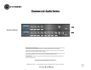
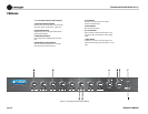
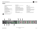
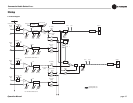
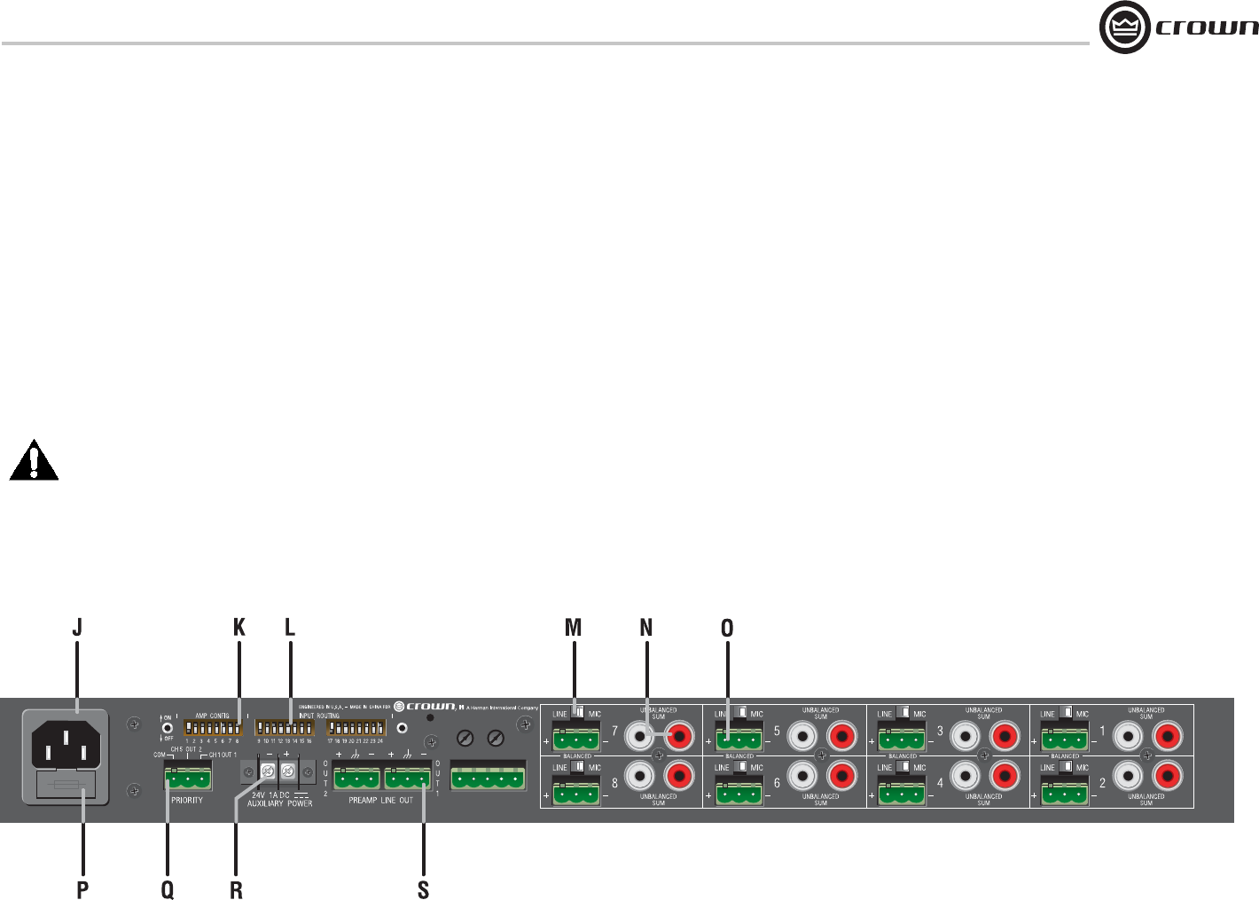
Figure 1.2 Back Panel Controls and Connectors
(28M shown)
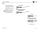
M. Mic/line Switch
Selects mic-level or line-level input signals. One switch for
each balanced input.
N. Dual RCA Input Connector
For stereo music signals, unbalanced, summed together,
two connectors per input channel. If required, both the mic/
line and RCA inputs may be used at the same time. The mic/
line gain switch does not affect the RCA gain, which is fi xed
relative to mic/line. The mic/line and RCA signals are mixed.
Note: Other equipment connected to the RCA jacks should
be connected to the same AC power source as the mixer to
avoid hum.
O. Mic/Line Input Connector
3-pin Phoenix-type, balanced, one per input channel.
P. Fuse
Protects the power supply.
Q Priority Connector
3-pin Phoenix-type connector allows Input 1 or Input 5
(28M only) to mute other input signals by contact closure.
R. Auxiliary Power Input
2-position terminal strip for 24 VDC (±10%) backup power.
Accepts up to 10 AWG terminal forks. NOTE: To prevent a
spark when attaching a battery, have unit turned on and
connected to the mains supply.
S. Line Out Connector
One 3-pin balanced Phoenix-type connector per output
channel. Level controlled by master volume control.
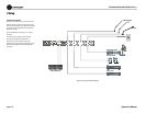
1.3 Back Panel Controls and Connectors
J. AC Power Inlet
Detachable IEC.
K. Mixer Confi g Switch
A DIP switch with two functions:
1. Assigns one of the inputs as the priority input for each
output, thereby temporarily muting the remaining inputs.
Muting is activated by contact closure.
2. Global enable switch for phantom power. Does not affect
RCA inputs. Default position is off.
L. Input Routing Switch (28M only)
DIP switches that assign each input signal to each output.
Two switches per input.
The tone generator has been omitted. Call Crown Tech
Sup port if you have tone generator questions.