


page 9
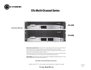
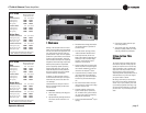
CTs Multi-Channel Power Amplifiers
Operation Manual
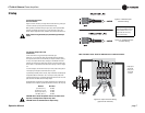
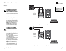
3.6.3 Bridge-Mono 16/8 Mode
CAUTION: Never change the position of
the Mode Switch while the amplifier
power is on. See Section 5.2.2 for more
information.
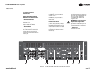
Typical input and output wiring, along with level
control and Mode Switch settings are shown in
Figure 3.8. Make sure the Mode switch is set to
the “Bridge 16/8” position.
INPUTS: Connect input wiring only to the lower-
(odd-) numbered channel pair.
OUTPUTS: Connect the speaker across the posi-
tive terminals of each channel pair. Do not use
the negative terminals of the channel pair when
the pair is being operated in Bridge-Mono mode.
NOTE: When operating the channel pair in
Bridge-Mono mode, turn down (full CCW) the
level control for the higher (even)-numbered
channel of the channel pair. The lower (odd)-
numbered level control works both channels.
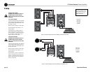
3.6.4 Bridge-Mono 100V Mode
CAUTION: Never change the position of
the Mode Switch while the amplifier
power is on. See Section 5.2.2 for more
information.
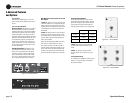
Typical input and output wiring, along with level
control and Mode Switch settings are shown in
Figure 3.9. Make sure the Mode switch is set to
the “Bridge 100V” position.
INPUTS: Connect input wiring only to the lower-
(odd-) numbered channel pair.
OUTPUTS: Connect the speaker across the posi-
tive terminals of each channel pair. Do not use
the negative terminals of the channel pair when
the pair is being operated in Bridge-Mono mode.
NOTE: When operating the channel pair in
Bridge-Mono mode, turn down (full CCW) the
level control for the higher (even)-numbered
channel of the channel pair. The lower (odd)-
numbered level control works both channels.
3 Setup
Figure 3.8 System Wiring and Control Settings, Bridge-Mono Mode, 16/8 Ohm.
Figure 3.9 System Wiring and Control Settings, Bridge-Mono Mode, 100V
CH 4
DUAL DUAL
BRIDGE
CH 3
CH 2
DUAL DUAL
BRIDGE
CH 1
See the Crown Amplifier Appli-
cation Guide, available online at
www.crownaudio.com, for pin
assignments for commonly
used connector types.
Output panel
shown with
touch-proof
cover plate
removed.
CH 4
DUAL DUAL
BRIDGE
CH 3
CH 2
DUAL DUAL
BRIDGE
CH 1
100V
Output panel
shown with
touch-proof
cover plate
removed.