


page 7
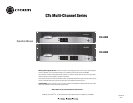
CTs Multi-Channel Power Amplifiers
Operation Manual
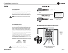
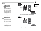
3.4 Choose Input Wire
and Connectors
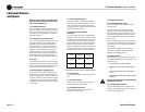
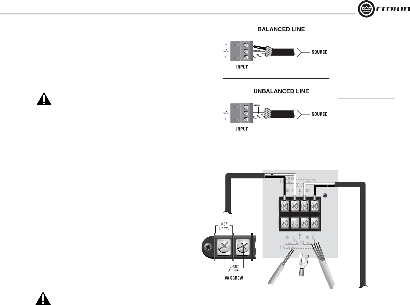
Figure 3.3 shows connector pin assignments for balanced wiring, and Figure
3.4 shows connector pin assignments for unbalanced wiring.
When possible, use balanced wiring for signal input, which provides better
rejection of unwanted noise and hum. For more information, refer to the
Crown Amplifier Application Guide, available online at www.crownaudio.com
NOTE: Custom wiring should only be performed by qualified per-
sonnel.
Figure 3.3 Balanced Input
Connector Wiring
Figure 3.4 Unbalanced Input
Connector Wiring
3 Setup
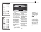
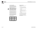
3.5 Choose Output Wire and
Connectors
Crown recommends using professionally constructed, high-
quality, two- or four-conductor, heavy gauge speaker wire and connectors.
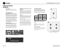
You may use terminal forks or bare wire for your output connectors (see Fig-
ure 3.5). CTs amplifier terminal strips accept up to 10 AWG terminal forks
which fit over a #8 screw. For best results, Crown recommends Panduit part
#PV10-10LF-L or equivalent terminal fork. Screw spacing is shown in Figure
3.5.
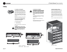
To connect outputs, first remove the touch-proof cover plate covering the ter-
minal strip by removing the screw which holds it in place.
To prevent the possibility of short-circuits, wrap or otherwise insulate exposed
loudspeaker cable and connectors. Also, a touch-proof cover plate, which
covers the terminal strips, is provided to help prevent short circuits. The cover
plate should be reinstalled after connecting outputs.
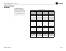
Suggested below are guidelines to select the appropriate size of wire based on
the distance from amplifier to speaker. Check with local code as this may vary.
Distance Wire Size
up to 25 ft (7.6 m) 16 AWG
26-40 ft (7.9-12.2 m) 14 AWG
41-60 ft (12.5-18.3 m) 12 AWG
Over 60 ft (18.3 m) 10 AWG
CAUTION: Never connect the speaker return to the chassis of the
amplifier, or damage to the amplifier may result.
CAUTION: Never use shielded cable for output wiring.
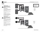
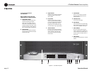
Figure 3.5 Output Connector Wiring
(Typical of two channels)
See the Crown Amplifier Appli-
cation Guide, available online at
www.crownaudio.com, for pin
assignments for commonly
used connector types.
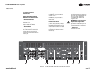
Output panel
shown with
touch-proof
cover plate
removed.
NOTE: CTs 8200 is shown. Some CTs 4200 features are in different locations.