


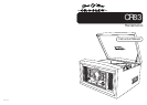


•Marking plate was located on bottom enclosure
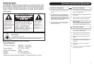
The exclamation point
within an equilateral
triangle is intended to
alert user to the
presence of important
operating and
maintenance (servicing)
instruction in the
literature accompanying
the appliance.
RISK OF ELECTRIC SHOCK
DO NOT OPEN
CAUTION
The lighting flash with
arrowhead symbol, within
an equilateral triangle, is
intended to alert user to
the presence of uninsulated
"dangerous voltage" within
the product's enclosure
that may be of sufficient
magnitude to constitute
risk of electric shock
to persons.
CAUTION: TO REDUCE
THE RISK OF ELECTRIC
SHOCK, DO NOT REMOVE
COVER (OR BACK). NO
USER - SERVICEABLE
PARTS INSIDE. REFER
SERVICING TO QUALIFIED
SERVICE PERSONNEL.
CAUTION
For Compact Disc Units Only:
INVISBLE LASER RADIATION WHEN OPEN AND INTERLOCK FAILED
OR DEFEATED. AVOID DIRECT EXPORSURE TO LASER BEAM.
Specification
Frequency Range : AM 520 - 1710 KHz
: FM 87.5 - 108.5 MHz
Power Supply : AC 120V ~ 60Hz
Power Consumption : 18W
Speed : 33 /45 /78 RPM
Speaker : 3” x 5” 8Ohm 5W x 2
WARNING:
TO PREVENT FIRE OR SHOCK HAZARD, DO NOT EXPOSE THIS
APPLIANCE TO RAIN OR MOISTURE. DO NOT REMOVE COVER.
PILOT LAMPS SOLDERED IN PLACE. NO USER SERVICEABLE
PARTS INSIDE. REFER SERVICING TO QUALIFIED SERVICE
PERSONNEL.
* DESIGN AND SPECIFICATIONS SUBJECT TO CHANGE WITHOUT NOTICE.
11
Connecting Optional Equipment
1 This radio is equipped with external speaker
outputs.
2 The speaker jacks for external speakers are
located on the back of the radio. Beside the
speaker jacks is a switch labeled (int./ext.) When
using external speakers, this switch must be
switched to the ext. position. Doing this turns off
the internal speakers in the radio and redirects
to power to the external speakers.
3 If you decide not to use the external speakers,
be sure the switch is on int. or the internal
speakers will not work.
1 You can connect your radio to different sources
using the auxiliary outputs.
2 Plug Auxiliary cables (not supplied) into the Line
Out Jack (32).
3 Connect the other end of the Auxiliary cables
into the input on your desired component.
4 See the owners manual for the component for
correct operation.
Note: The Auxiliary Output only puts out a signal.
External speakers by themselves must be
hooked up to the External Speaker Jacks (33).
1 You can connect external components to your
unit by using the Auxiliary Inputs.
2 Plug Auxiliary cables (not supplied) into the
INPUT JACK (37) on the back of your unit.
3 Switch the LINE IN ON/OFF (36) to the ON
position.
4 Plug the other end of the Auxililary cables into
the output jack on your desired external
component.
5 Check the volume level of your external
component.
6 See operators manual for correct operation of
the external component.
External Speakers Auxiliary Outputs
Auxiliary Inputs