


Professional Balanced Audio Receiver Crestron CNX-PBAR4
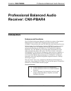
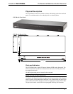
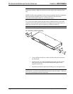
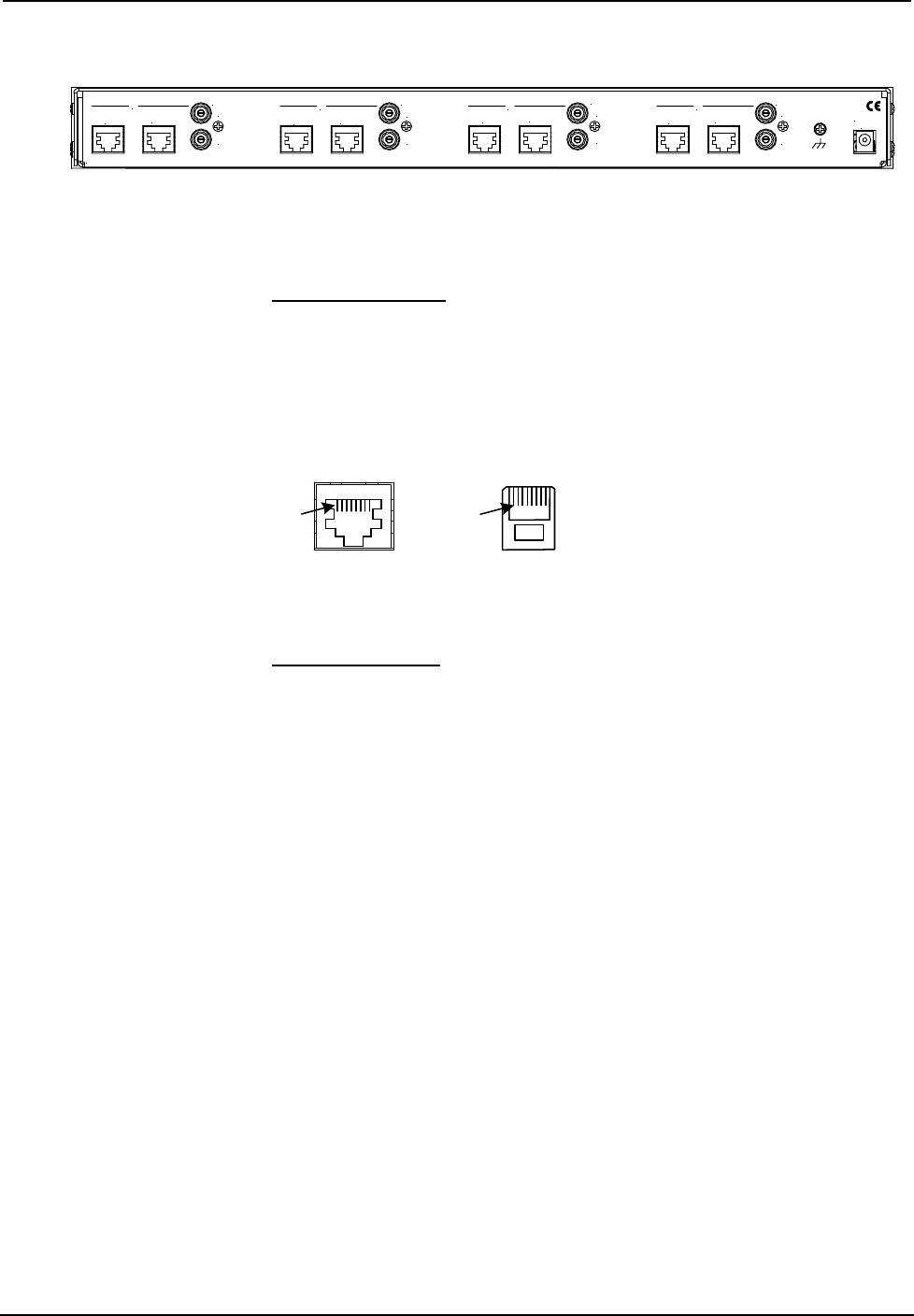
CNX-PBAR4 Rear Panel
24VDC
1A
CRESTRON ELECTRONICS INC., ROCKLEIGH, NJ 07647 USA
AUDIO OUT
LEFT
RIGHT
IN
OUT
AUDIO OUT
LEFT
RIGHT
IN
OUT
AUDIO OUT
LEFT
RIGHT
IN
OUT
AUDIO OUT
LEFT
RIGHT
IN
OUT
1
2
3
4
Each of the four audio channels consists of two RJ45 (8-pin) connectors (labeled IN
and OUT) and a pair of gold plated RCA connectors labeled AUDIO OUT, LEFT
and RIGHT.
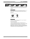
RJ45 Connectors
These 8-pin connectors provide bi-directional balanced audio connection, via CAT5
cables, to CNXRMCLV room boxes and to CNX-BIPAD8 audio distribution
processors. Pinouts for the unit receptacles and cable connectors are shown in the
following figure.
RJ45 Pinouts
CONNECTOR
(TAB FACING AWAY
8 PIN, RJ45 PINOUT
RECEPTACLE, REAR VIEW
(TAB POSITION DOWN) )
Pin 1
Pin 1
RCA Connectors
The two RCA connectors provide line-level audio for a variety of configurations
required by the local equipment in the room.
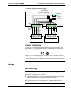
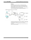
Functional Description
As shown in the simplified functional diagram on the following page, the IN
connectors receive balanced audio input from the CNXRMCLV on pins 1, 2, 3, and
6. The balanced audio is buffered, routed to pins 1, 2, 3, and 6 of the OUT connector,
and supplied to the CNX-BIPAD8. The balanced audio is also converted to
unbalanced audio and supplied to the RCA connectors for distribution to the CNX-
BIPAD8, amplifiers, or other room boxes. Balanced audio from the CNX-BIPAD8 is
supplied to pins 4, 5, 7, and 8 of the OUT connector, and passed through to pins 4, 5,
7, and 8 of the IN connector, to be supplied to the CNXRMCLV.
4 • Professional Balanced Audio Receiver: CNX-PBAR4 Operations Guide – DOC. 8183