


12
CREATIVE
DTT 3500 DIGITAL
MUMO
FOURP
DOL
BY
DOLBY AUDIO
SPEAKE
MU
LR
MAST CENT
SUBWOOF
SURROU
PRO
ANALO
DIGITA
POWE
STERE
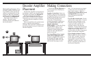
Decoder Amplifier
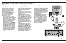
Placement
N
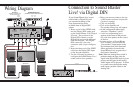
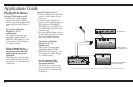
Making Connections
Consult the Wiring Diagram on
the next page before making any
connections.
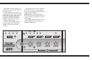
Speaker Connections. Insert one
satellite’s plug into the correspond-
ing Speaker Output on the Decoder
Amplifier. Repeat this process for
the remaining satellites and
subwoofer. If substituting a
powered subwoofer, connect it to
the SUBWOOFER LINE OUT.
Signal Connections.
Dolby Digital. Connect the Dolby
Digital/SPDIF output of your
signal source to the Decoder
Amplifier’s Dolby Digital input
using the cable with the RCA
plugs at each end.
For Sound Blaster Live! sound
cards with a digital I/O card:
Connect its Digital DIN output to
the Digital DIN input with the
supplied Digital DIN cable (the
one with the red plugs at each
end). It is not necessary to connect
a cable to the Line In and Rear In
input in this instance. Refer to
Connection to Sound Blaster Live!
via Digital DIN (next page) for
more information about this
connection.
For all other sound cards: Use the
tandem audio signal cable. Connect
the green stereo miniplugs to the
Line Out minijack output of your
sound card and to the Line In
minijack output of the Decoder
Amplifier. Connect the black stereo
miniplugs to the Rear Out minijack
output of your sound card (if
present) and to the Rear In minijack
input of the Decoder Amplifier.
Power Supply Adapter Connec-
tions. Confirm the power switch is
in the “OFF” position. Insert the
power supply’s AC plug into an
appropriate receptacle. Insert the
small DC connector into the “15V
DC IN” receptacle on the back of
the Decoder Amplifier.
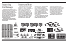
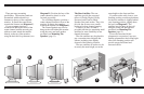
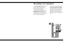
Hook and Loop Fasteners: When
mounting speakers with hook and
loop fasteners, make sure that all
surfaces are clean and free of dirt
and grease. Hard, flat, unpainted
surfaces work best with hook and
loop fasteners (see Diagram M).
Attach the fastener first to a
speaker. Then remove the
remaining backing and adhere to
the chosen surface.
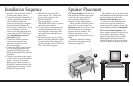
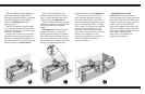
The Decoder Amplifier can be placed on
the desktop, a shelf or any site that makes
the controls convenient (see Diagram N).
The Power Adapter cord must be
able to reach from the Decoder Amplifier
back panel to your AC power receptacle.
Place the Decoder Amplifier on a hard,
flat surface.
There are ventilation slots on the bottom
and top of the Decoder Amplifier’s
enclosure. Don’t block the ventilation slots
by placing material on top of or below the
Decoder Amplifier.
CREATIVE
DTT 3500 DIGITAL
MUMO
FOURP
DOL
BY
DOLBY AUDIO
SPEAKE
MU
LR
MAST CENT
SUBWOOF
SURROU
PRO
ANALO
DIGITA
POWE
STERE
M