


7
SPA-1400/1400C Rack Mount Power Amplifier
Speakon
®
is a registered trademark of Neutrik USA
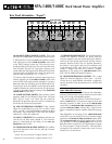
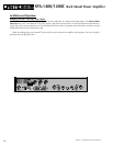
Speaker Impedances And Power Ratings:
When connecting speaker cabinets, you must observe proper load impedances. Whenever connecting multiple cabinets to an
amplifier, the total load impedance must be calculated to insure proper performance from the amplifier. The table which follows
shows the total load impedances of many common parallel speaker combinations:
Power Output:
The power output of an amplifier changes as the total load impedance increases or decreases. The chart below shows the
increase in the total output power of the SPA-1400/1400C as the total load impedance decreases:
total load impedance (in ohms): 8 (stereo) 4 (stereo) 2 (stereo) 16 (mono) 8 (mono) 4 (mono)
total output power (watts RMS): 260/channel 425/channel 660/channel 520 850 1320
Output Power Per Speaker Cabinet:
If each parallel connected speaker cabinet has the same rated impedance, divide the total power output by the number of cab-
inets used. For example: Four 16 ohm cabinets have a total load impedance of 4 ohms (see the impedance chart above), which
allows a total output power of 425 watts RMS (Stereo Mode): 400/4 = 108 watts RMS for each cabinet.
Speaker cabinets with different rated impedances will draw different amounts of power. To calculate the power output per cab-
inet, obtain the total load impedances from the impedance chart above and divide it by each speaker impedance. For example:
Three speaker cabinets, one with a rated impedance of 8 ohms and two at 16 ohms are connected in parallel. According to the
impedance chart, the total load impedance is 4 ohms, which means a total power output of 425 watts as above. Divide the total
impedance by the impedance of each speaker and multiply the results by 425.
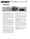
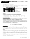
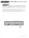
Input/Output Connectors:
The SPA-1400/1400C uses both XLR type and 1/4" phone jacks as input connectors for each channel. These inputs accept
Medium or Low impedance balanced or unbalanced signals. When using a 1/4" plug to feed a balanced signal into the amplifier,
tip = signal “+”, ring = signal “–”, sleeve = ground. When using a 1/4" plug to feed an unbalanced signal into the amplifier, tip =
signal “+”, sleeve = ground. On the SPA-1400C, additional XLR Balanced Thru/X-Over Out jacks are available. Each jack can be in
parallel with the XLR and 1/4” input jacks directly below them - set the X-Over Out/Thru switch to the “thru” position (switch not
pressed in).
On each channel, both input jacks are wired in parallel; when one jack is used as an input, the remaining jack may be used to obtain
a line out signal. In both Mono Modes, Channel 1’s input jacks are used; Channel 2's input jacks are disconnected.
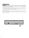
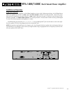
Each channel has both 5-way binding posts and a Speakon
®
jack. A third Speakon
®
jack is provided for Mono/ Bridge use and
can also be used for biamping. On each channel, the binding posts are wired in parallel with the Speakon
®
jacks. Use of both the
binding posts and the Speakon
®
jacks simultaneously to connect cabinets in parallel is possible, providing proper polarity and imped-
ance is observed.
The Channel A and B Speakon
®
jacks are wired as follows: pin 1+ = “+”, pin 1– = “–” . The Mono/Biamp (middle) Speakon
®
jack is wired as follows: Pins 1+ and 1– = Channel 1 “+” and “–” respectively; pins 2+ and 2– = Channel 2 “+” and “–” respec-
tively. See pages 8 – 20 for Speakon
®
wiring information.
4Ω 8Ω 16Ω 4:4Ω 4:8Ω 4:16Ω 8:8Ω 8:16Ω 16:16Ω
2Ω 2.7Ω 3.2Ω 1.3Ω 1.6Ω 1.8Ω 2Ω 2.3Ω 2.7Ω
2.7Ω 4Ω 5.3Ω 1.6Ω 2Ω 2.3Ω 2.7Ω 3.2Ω 4Ω
3.2Ω 5.3Ω 8Ω 1.8Ω 2.3Ω 2.7Ω 3.2Ω 4Ω 5.3Ω
1.3Ω 1.6Ω 1.8Ω 1Ω 1.1Ω 1.2Ω 1.3Ω 1.5Ω 1.6Ω
1.6Ω 2Ω 2.3Ω 1.1Ω 1.3Ω 1.5Ω 1.6Ω 1.8Ω 2Ω
1.8Ω 2.3Ω 2.7Ω 1.2Ω 1.5Ω 1.6Ω 1.8Ω 2Ω 2.3Ω
2Ω 2.7Ω 3.2Ω 1.3Ω 1.6Ω 1.8Ω 2Ω 2.3Ω 2.7Ω
2.3Ω 3.2Ω 4Ω 1.5Ω 1.8Ω 2Ω 2.3Ω 2.7Ω 3.2Ω
2.7Ω
4Ω
SYSTEM TWO
ONE
SPKR
SINGLE SPEAKER
SYSTEM ONE
TWO SPEAKERS IN PARALLEL
TWO IN
PARALLEL
8Ω
16Ω
4:4Ω
4:8Ω
4:16Ω
8:8Ω
8:16Ω
16:16Ω 4Ω 5.3Ω 1.6Ω 2Ω 2.3Ω 2.7Ω 3.2Ω 4Ω
The formula for this chart is:
1
1/R
1
+ 1/R
2
+ ... + 1/R
N
Where “R” is the speaker impedance. So, using two 16 ohm
speakers in combination with one 8 ohm speaker, the imped-
ance would be:
111
1/8 +1/16+1/16 .125+.0625+.0625 .250
= 4 ohm load impedance
You can also figure this on the table. On System One, match
the “16:16” column with the System Two “8” row.
=
=
R
total
_____ = 4/8 = 1/2 x 425 = 217.5 watts for the 8 ohm cabinet
R
N
4/16 = 1/4 x 425 = 108.75 watts for each of the 16 ohm cabinets
Note that some combinations
result in impedances less than 2
ohms. (the shaded areas) These
combinations are not
recom-
mended for the SPA-1400/1400C
and should be avoided. They are
included on the chart for refer-
ence only. Too low an impedance
will activate the amplifier’s pro-
tection circuit.