


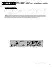
SPA-1400/1400C Rack Mount Power Amplifier
(
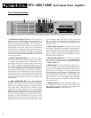
SPA-1400C ONLY
)
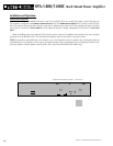
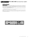
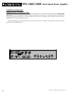
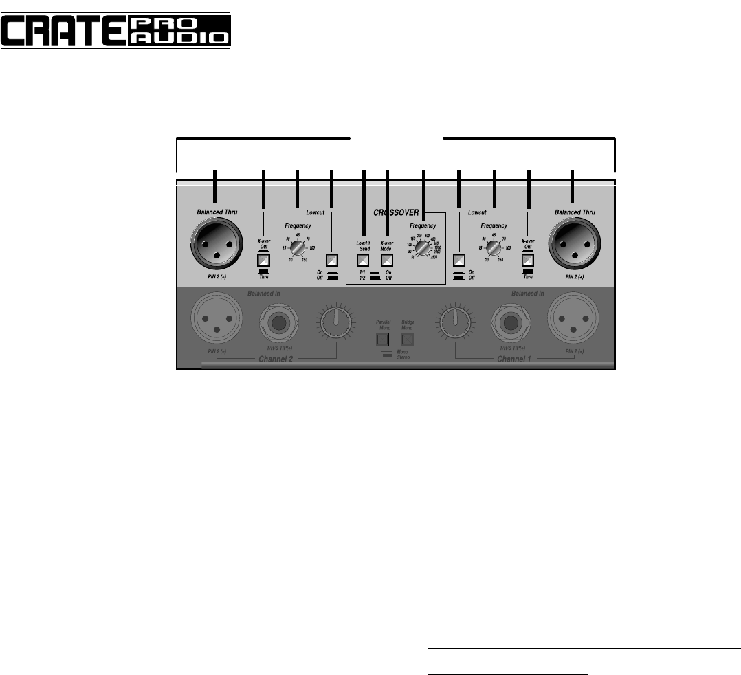
18 1920 21 22 23 2119 182024
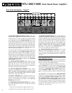
18: BALANCED THRU/X-OVER OUT JACKS: These male
XLR jacks are independently switchable and have two uses:
(1) Balanced Thru: For driving additional amplifiers with the
same input signal, set the X-OVER OUT/THRU switch (#19)
to the THRU position (switch out). This places its corre-
sponding Balanced Thru/X-Over Out jack in parallel to the
same channel’s XLR and 1/4” input jacks. Connect a bal-
anced cable with XLR plugs from the Balanced Thru/X-Over
Out jack of the first amplifier to the input jack of the next.
Wire the cable as follows: pin 2 = “+”, pin 3 = “–”.
(2) Crossover Out: To send the crossover output signal to an
external amplifier, set the X-OVER OUT/THRU switch (#19)
to the X-OVER OUT position (switch pressed in). Connect a
balanced cable with XLR plugs from the Balanced Thru/X-
Over Out jack of the first amplifier to the input of the other
amplifier. Whether the jack carries the low or high frequen-
cy signal is dependent upon the setting of the CROSSOVER
HI/LOW SEND
switches (#22).
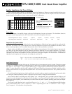
19: X-OVER OUT/THRU SWITCH: These switches set the
operating mode for the Balanced Thru/X-Over Out jacks
(#18). Set the switch “out” (flush with the panel) for
Balanced Thru operation; press the switch in (recessed into
the chassis) for Crossover Out operation.
20. LOW CUT FREQUENCY CONTROLS: These controls
adjust the cut-off frequency of the low cut filters (when
active – see #21). Use a small flatblade screwdriver to adjust
the controls. The cut-off range is from 10Hz (full counter-
clockwise) to 150Hz (full clockwise).
21: LOW CUT SWITCHES: These pushbutton switches acti-
vate the low cut filters when pressed in. The cut-off fre-
quency is determined by the setting of the
LOW CUT
FREQUENCY
control (#20).
22: CROSSOVER LOW/HI SEND SWITCH: This pushbut-
ton switch determines where the low and high crossover
signals are sent:
Switch IN: Low to channel 2, High to channel 1 (2/1)
Switch OUT: Low to channel 1, High to channel 2 (1/2)
23: CROSSOVER MODE SWITCH: This switch determines
whether the amplifier channels are driven from the
crossover outputs or from the normal input signal. With the
switch in the “off” position (pressed out), the amp is driven
normally. With the switch in the “on” position (pressed in),
the channel 1 input signal is split into a low frequency and
a high frequency signal. One signal is sent to the amp’s
channel 1 outputs, the other to its channel 2 outputs,
depending on the setting of the LOW/HIGH SEND switch
(#22). (See the additional information below.)
24: CROSSOVER FREQUENCY CONTROL: This control
adjusts the crossover frequency (when active – see #23).
Use the tip of a small flatblade screwdriver to adjust the
control, from 45Hz (full counterclockwise) to 2500Hz (full
clockwise).
More About the Crossover:
The electronic crossover is ideal for use with subwoofers
and may also be used to crossover from low to mid, mid to
high or low to high on biampable speakers.
The input signal to the crossover is taken from channel 1,
after the LOW CUT filter. The crossover output may be used
internally, externally, or both, by use of the LOW/HI SEND
switch (#22), the BALANCED THRU/X-OVER OUT jacks (#18),
and the X-OVER OUT/THRU switches (#19). A signal can be
sent to a completely separate amplifier if desired (see page
17).
Note: Regardless of the setting of the CROSSOVER MODE
switch (#23), you can still take a line level crossover output
signal from the BALANCED THRU/X-OVER OUT jacks (#18).
The X-OVER OUT/THRU switch (#19) must be set to “X-Over
Out” (pressed in), and the LOW/HI SEND switch (#22) will
determine where to tap the low and high frequency signals
(ie, lows to channel 2, highs to channel 1 when the switch
is pressed in). The crossover is always active, even if it is not
selected “on” for internal use.
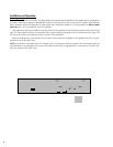
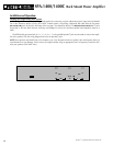
Rear Panel Information – “Export”:
6