


4
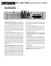
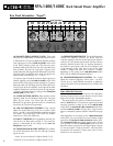
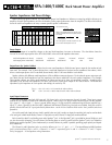
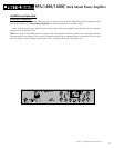
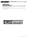
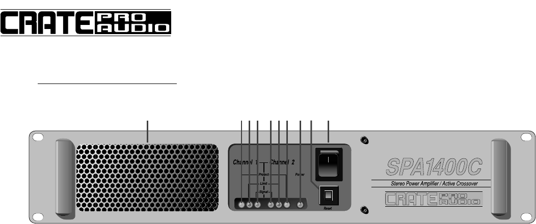
Front Panel Information:
1 4 3 22 3 4 5 6 7
1: COOLING FAN EXHAUST VENT: The SPA-1400/1400C
employs a pair of variable-speed internal cooling fans to
draw air through the unit and keep it running cool even
under extreme operating conditions. The air is drawn in
through the unit’s side and rear intake vents and is forced
out through the front panel exhaust vent. This method of
cooling draws air out from the interior of the rack and pro-
vides more efficient cooling than methods which bring air
in from the front and exhaust it through the back. Keep
these vents clear and free from obstruction at all times to
insure proper cooling.
2: PROTECT INDICATOR LEDS: These LEDs will illumi-
nate whenever the internal protection relay for the channel
is activated. The protection relay is activated for a short
period upon initial turn-on and at turn-off to prevent tran-
sient “spikes” from being reproduced through your speak-
ers. A protect condition is also indicated if the unit gets too
hot, or if DC voltages are present at the output. During ther-
mal protection, both channels are shut down until the tem-
perature returns to a safe operating level. In the event of DC
voltage on the output, only the affected channel will be dis-
connected. The circuitry associated with the LED indicators
provides valuable protection for both the amplifier and
your speakers.
3: LIMIT INDICATOR LEDS: The SPA-1400/1400C
employs an internal “Automatic” limit circuit to prevent the
amplifier from clipping. The Limit LEDs will illuminate
whenever the input signal attempts to overdrive the ampli-
fier’s output section, indicating that the Limiter has been
called upon to prevent clipping. (Not only does clipping
produce harsh sounding distortion, it is also capable of
damaging speaker components – particularly high frequen-
cy drivers.) Periodic flashing of the Limit LEDs indicates
operation at or near full output and is no cause for alarm.
Steady illumination of one or both LEDs indicates constant
operation of the Limiter, with the possibility that the input
signal should be reduced by means of the Level control
(#15, rear panel). The Limiter within the amplifier is fully
automatic, insuring you complete protection against clip-
ping at all times.
4: SIGNAL INDICATOR LEDS: These LEDs will illuminate
when signal is detected at the amplifier’s output terminals,
providing accurate visual confirmation of signal presence,
which is helpful in hookup and troubleshooting. The out-
put signal must be at least 5% of the amplifier’s full rated
output to make the LEDs glow.
5: POWER INDICATOR LED: This LED will illuminate
when AC power is applied by means of the POWER SWITCH
(#7). If the LED fails to illuminate, check the AC outlet or
the RESET SWITCH (#6).
6: RESET SWITCH: The SPA-1400/1400C employs an AC
line circuit breaker to help protect against damages due to
excessive current demands. If the amplifier does not func-
tion, check the circuit breaker. If it has opened, the button
will be protruding and showing a contrasting color. You
may reset it by pressing the button in until it latches. The
circuit breaker must cool down for a short time before the
button will latch. If the circuit breaker opens repeatedly
with no signal input, have the amplifier checked by a qual-
ified service person.
7: POWER SWITCH: This switch turns the amplifier on in
the up position (“I” pressed in) and off in the down posi-
tion. When AC power is applied to the amplifier, the
POWER INDICATOR LED (#5) will illuminate.
SPA-1400/1400C Rack Mount Power Amplifier