


6
Speaker Impedances And Power Ratings:
When connecting speaker cabinets, you must observe proper load impedances. Whenever connecting multiple cabinets to
an amplifier, the total load impedance must be calculated to insure proper performance from the amplifier. The impedance chart
which follows shows the total load impedances of many common parallel speaker combinations:
Power Output:
The power output of an amplifier changes in accordance with the load impedance or mode of operation. The total output
power of the SPA100 is as follows:
total load impedance: 8 ohms 4 ohms
total output power: 75 watts 100 watts
Output Power Per Speaker Cabinet:
If each parallel connected speaker cabinet has the same rated impedance, divide the total power output by the number of cab-
inets used. For example: Four 16 ohm cabinets have a total load impedance of 4 ohms (see the impedance chart above), which
allows a total output power of 100 watts RMS: 100/4 = 25 watts RMS for each cabinet.
Speaker cabinets with different rated impedances will draw different amounts of power. To calculate the power output per
cabinet, obtain the total load impedances from the impedance chart above and divide it by each speaker impedance. For exam-
ple: Three speaker cabinets, one with a rated impedance of 8 ohms and two at 16 ohms are connected in parallel. According
to the impedance chart, the total load impedance is 4 ohms, which means a total power output of 100 watts as above. Divide
the total impedance by the impedance of each speaker and multiply the results by 100.
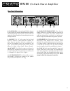
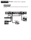
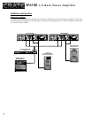
Joining Two Amplifiers For Rack Mounting:
The SPA100 amplifier is shipped with a heavy duty
steel joining plate (not attached to the unit). This allows
two amplifiers to be mounted side by side in a single
rack space (19”W x 1-3/4”H).
(1) Remove one rack mount flange from each amplifier:
the flange on the right side of the amplifier on the left and
the flange on the left side of the amplifier on the right.
(2) Remove two front panel screws from each amplifier:
the two screws on the right side of the amplifier on the
left and the two screws on the left side of the amplifier
on the right.
(3) Position the amplifers side by side, align the holes in
the joining plate with the holes in the front panel of the
adjacent amplifier. Insert the screws through the joining
plate into the front panel of the adjacent amplifier and
tighten securely.
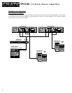
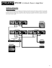
The formula for this chart is:
1
1/R
1
+ 1/R
2
+ ... + 1/R
N
Where “R” is the speaker impedance. So, using two 16 ohm
speakers in combination with one 8 ohm speaker, the imped-
ance would be:
111
1/8 +1/16+1/16 .125+.0625+.0625 .250
= 4 ohm load impedance
You can also determine the combined impedance by means
of the Impedance Chart. The combined impedance appears at
the intersection of the 16:16 column (System One) and 8Ω
row (System Two).
=
=
R
total
_____ = 4/8 = 1/2 x 100 = 50 watts for the 8 ohm cabinet
R
N
4/16 = 1/4 x 100 = 25 watts for each of the 16 ohm cabinets
SYSTEM ONE
TWO SPEAKERS
IN PARALLEL
SINGLE SPEAKER
8
8:16 16:1616
16
8:16
16:16
8
ONE
SPKR
SYSTEM
TWO
TWO IN
PARALLEL
4
5.3
5.3
5.3
3.2
3.2
3.2
4
4 2.7
8 4
4
5.3
3.2
4
Note that some combinations result in impedances less than 4 ohms. (the shaded areas) These combi-
nations are not
recommended for the SPA100 and should be avoided. They are included on the chart for
reference only. Too low an impedance will activate the amplifier’s protection circuit.
IMPEDANCE CHART:
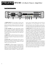
SPA100 1/2-Rack Power Amplifier
Power
Power
On
Off
Signal Limit Protect
Power
Power
On
Off
Signal Limit Protect
Power
Power
On
Off
Signal Limit Protect
Power
Power
On
Off
Signal Limit Protect
REMOVE THESE 2
RACK MOUNT FLANGES
REMOVE THE 6
SIDE SCREWS
(3 PER UNIT)
REMOVE THESE 2
FRONT SCREWS
REMOVE THESE 2
FRONT SCREWS
PLACE UNITS SIDE BY SIDE - ALIGN THROUGH HOLES
IN JOINING PLATE OVER SCREW HOLES IN UNITS
TWO UNITS, JOINED AND READY FOR RACK MOUNTING:
INSERT 4
FRONT SCREWS
Power
Power
On
Off
Signal Limit Protect
Power
Power
On
Off
Signal Limit Protect