


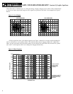
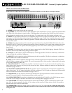
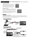
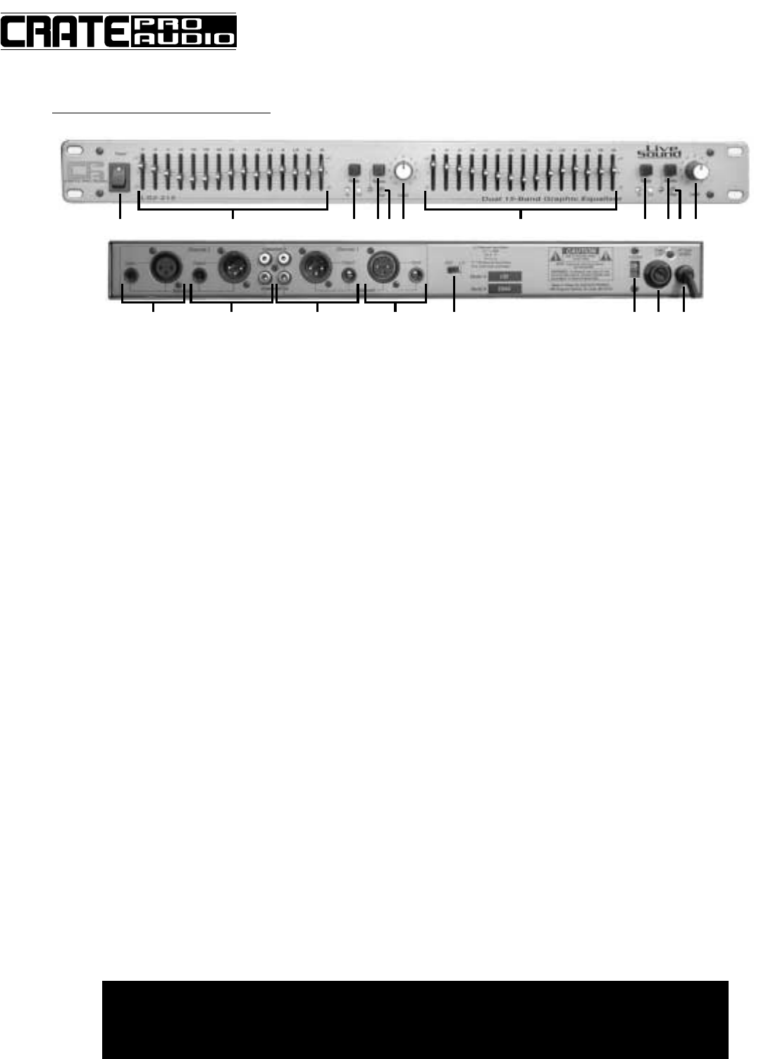
The LS2-215 Front and Rear Panels:
1 - POWER: Use this switch to turn the unit on and off.
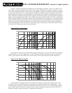
2 - EQ SLIDERS: Use these slide controls to make adjustments at the standard ISO 2/3-octave frequencies indicated above
each slider. Each slider adjusts the signal ±6dB or ±12dB depending on the setting of the RANGE switch (#3). Moving a
slider up boosts the signal; moving it down cuts the signal. The center detent is the “flat” position (no boost or cut).
3 - RANGE: Use this switch to select one of two adjustment ranges for the EQ sliders (#2). With the switch out, the adjust-
ment range is ±12dB. When this switch is depressed, the adjustment range is ±6dB. Care should be taken not to acciden-
tally change the range from 6dB to 12dB during operation if extreme boosts are used, since the boosts will dramatically
increase if this occurs.
4 - BYPASS: When depressed, this switch routes the input signal directly from the BALANCED INPUT jacks (#7) to the
BALANCED OUTPUT jacks (#8), bypassing the equalizer controls completely. This is useful when comparing the equal-
ized signal to the original. The adjacent LED (linked graphically to the switch with a solid line) glows red when in the
bypass mode.
5 - PEAK LED: This indicator glows red when the input or output signal is within 5dB of clipping. Adjust the LEVEL con-
trol (#6) so this LED only flashes during strong, peak-level signals.
6 - LEVEL: Use this control to adjust the input signal level. For the best signal to noise ratio set this control so the PEAK
LED (#5) flashes on strong, peak-level signals. The overall output signal level of the equalizer is determined by the setting
of this control and the EQ sliders (#2).
7 - BALANCED INPUTS: The mixing board, amplifier or instrument (“source”) may be connected to the equalizer using
either of these jacks. However, only one jack may be used at a time. Different methods of connection are described and
illustrated on pages 9 and 10.
8 - BALANCED & UNBALANCED OUTPUTS: The equalizer may be connected to the mixing board or amplifier using
either of these jacks. The 1/4” phone jack and the XLR jack are balanced. The RCA jacks are unbalanced. Different meth-
ods of connection are described and illustrated on pages 9 and 10.
9 - GROUND LIFT: Use this switch to electronically disconnect the signal ground from the mains and chassis earth
ground. This may be helpful in eliminating ground loops which cause hum.
10 - VOLTAGE SELECTOR: The equalizer is designed to be used with either 95-130VAC or 190-250VAC power sources.
Check the AC line voltage of the outlet and set this switch accordingly before plugging in the unit.
11 - FUSE HOLDER: This contains the fuse for the AC mains. If the fuse blows, replace it with only the same size and
type. If the fuse blows repeatedly, check the AC line voltage and the equalizer’s voltage selector switch. If the problem
persists contact your Crate Pro Audio dealer.
12 - POWER CORD: Connect the power cord to a suitable source of AC line voltage. Be sure to match the voltage selector
switch (#10) to the line voltage before making this connection! In order to reduce the risk of shock, DO NOT defeat the ground pin
of the power cord!
LS1-131/LS2-215/LS3-231
Constant Q Graphic Equalizers
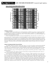
1 2 43 5 6 2 44 5 6
7 978 8 1110 12
IMPORTANT! PLEASE NOTE: The equalizers are equipped with a voltage selector switch (12 on
page 6, #10 on page 7). BEFORE PLUGGING THE EQUALIZERS INTO AN AC OUTLET, MAKE SURE
THE VOLTAGE SELECTOR SWITCH IS SET TO THE CORRECT RANGE FOR THE AC SOURCE!
Improper switch setting may harm the equalizer!
7