


CA120D Acoustic Amplifier
5
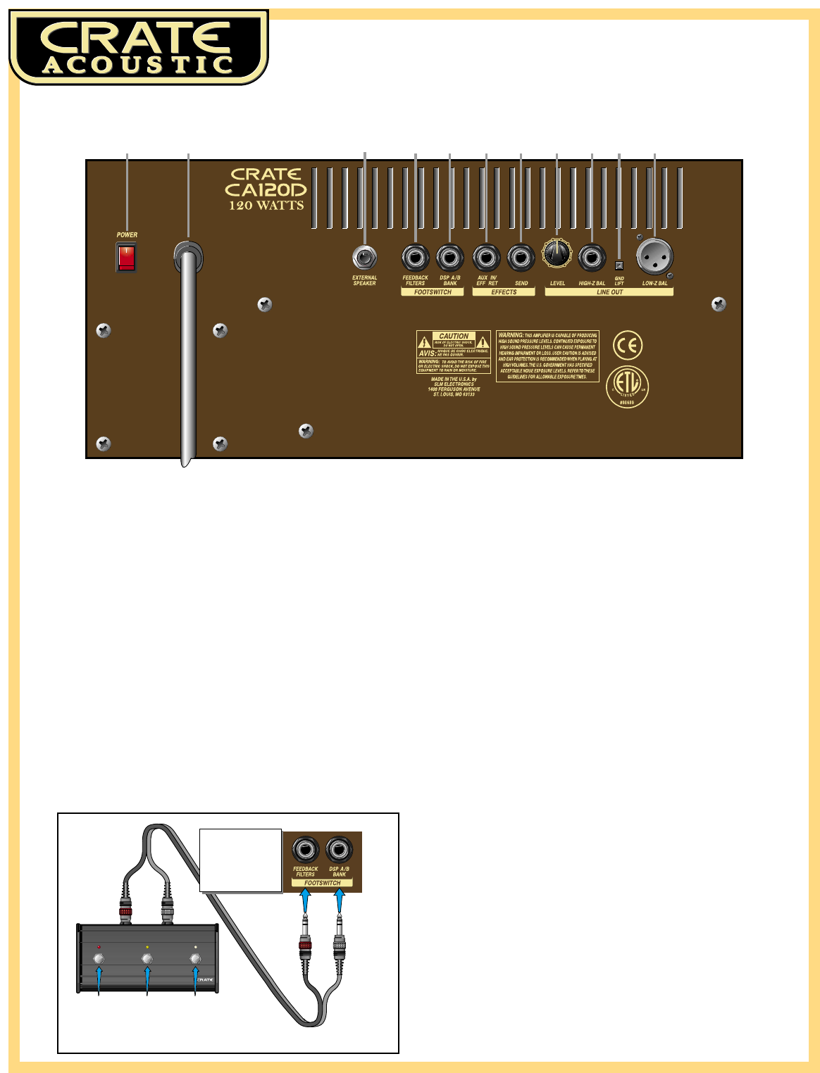
19 20 21 22 23 24 25 26 27 28 29
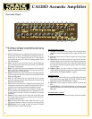
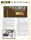
The Rear Panel:
19: Power. Use this switch to turn the amplifier on (top of the switch
depressed) and off (bottom of the switch depressed.) The power
switch illuminates when the amplifier is on.
20: AC Line Cord. The grounded power cord should only be plugged
into a grounded power outlet that meets all applicable electrical
codes and is compatible with the voltage, power and frequency
requirements stated on the rear panel. Do not attempt to defeat the
safety ground connection!
21: External Speaker. Use this jack to connect the amplifier to an external
speaker cabinet. This jack is wired in series with the internal speakers
which remain active when an external speaker is connected.
22: Feedback Filters Footswitch. Connect the three-button footswitch to
this jack for remote control of the feedback filters. The Feedback
Filters ON LED (#14, front panel) illuminates and the feedback circuit
is activated when a footswitch is connected to this jack. Footswitch
button #1 controls Feedback Filter 1, button #2 controls Filter #2. (See
illustration below.)
Note: This is a STEREO jack: tip = Filter 1, ring = Filter 2, sleeve is
ground. Use only a footswitch equipped with a stereo 1/4” plug.
23: DSP A/B Bank Footswitch. Connect the three-button footswitch to
this jack for remote control of two DSP settings:
1.With footswitch button #3’s LED illuminated, select one of the DSP
settings
2.Step on footswitch button #3 - the LED will go out - select a differ-
ent DSP setting
3.Step on footswitch button #3 again - the LED illuminates, and the
DSP automatically changes back to the setting chosen in step 1.
4.Step on footswitch button #3 again - the LED goes out, and the DSP
automatically changes back to the setting chosen in step 2.
24: Effects Aux In/Eff Ret. When using an external signal processor or any
line level signal (drum machine, keyboard, etc), connect the output of the
device to this jack by means of a shielded signal cable.
25: Effects Send. When using an external signal processor, connect this
jack to the input of the effect by means of a shielded signal cable.
26: Line Out Level. Use this control to adjust the output level of the line
out signal. (This control works independently from the amplifier’s
master level control.)
27: High Z Bal Line Out. Use this jack to connect a high impedance, line
level signal to a house sound board, a recording console or an exter-
nal power amplifier by means of an 1/4” stereo plug-terminated
cable. (Ring is signal +, tip is signal -, and sleeve is ground.)
28: Gnd Lift. This switch, when depressed, electronically disconnects
both of the Line Out jacks’ (#27, #29) chassis ground connections. If
you experience excessive noise when using the Line Out jacks,
depress this switch.
29: Low Z Bal Line Out. Use this jack to connect a low impedance, line
level signal to a house sound board, a recording console or an exter-
nal power amplifier by means of an XLR-terminated cable. (Pin 1 is
ground, pin 2 is signal +, and pin 3 is signal -.)
Butto
n
#
1
:
Tu
rn
s
Feedback
Filter #1
on and off
Butto
n
#2:
Tu
rn
s
Feedback
Filter #2
on and off
Butto
n
#3:
T
o
gg
e
s
bet
w
ee
n
DSP
settings
CA120D Rear Panel:
3
2
1
3
2
1
NOTE: The Feedback
circuit is activated
when a footswitch is
plugged into the
Feedback Filters
Footswitch jack ---->