


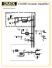
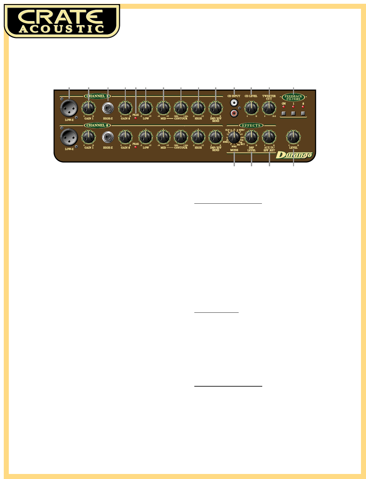
CA120D Acoustic Amplifier
4
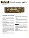
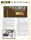
1
15 16 17 18
2 4 6 7 8 9 10 11 12 13 1453
NOTE: Channel 1 and Channel 2 are independent of each other up
to the Effects and Master sections. The text below (#1–10)
applies to both channels.
1: Low-Z. The signal from a low impedance microphone may be con-
nected here by means of a shielded, balanced microphone cable ter-
minated with an XLR connector. This jack has 15 volts phantom
power applied to pins 2 and 3. (Mics not requiring phantom power
will not be affected.)
2: Gain 1. This serves as the input level control for the XLR Input jack
(#1). For the best signal to noise ratio set this control so the Peak LED
(#5) flashes on strong signals.
3: High-Z. The signal from your acoustic instrument may be connected
here by means of a shielded signal cable. This input will accommo-
date a piezo pickup or an active system.
4: Gain 2. This serves as the input level control for the High-Z jack (#3).
For the best signal to noise ratio set this control so the Peak LED (#5)
flashes on strong signals.
5: Peak. This LED flashes when the signal level into the preamp
approaches clipping. Adjust the Gain controls (#2, #4) until a strong
signal causes this LED to flash.
6: Low. This serves as the bass control. Adjust this control to get the best
sounding bass response for this channel. Excessive boost of the low
control can cause an unnatural howling and should be avoided.
7: Mid. This serves as the midrange control. Adjust this control to get
the best projection and midrange tones for your instrument. The cen-
ter point of the mid control is chosen by the setting of the Contour
control (#8).
8: Contour. Use this control to set the center point of the Mid control
(#7). Set this control at the frequency which gives you the most natu-
ral-sounding midrange tones.
9: High. This serves as the treble control. Adjust this control so your
high notes and harmonic overtones are lively but not overpowering.
10: DSP/Eff Send. Use this control to adjust the amount of internal
Digital Effect and/or external effect (if used).
The Master Section - part one:
11: CD Input. Use these RCA jacks to connect a CD or tape player to the
amplifier. Use the CD Level control (#12) to adjust the level of the
player.
12: CD Level. Use this control to adjust the signal level at the CD Input
jacks (#11).
13: Tweeter Cut. Use this control to reduce the output level of the inter-
nal high frequency driver. In the fully counter-clockwise position, the
tweeter is at its full output level. As you rotate the control clockwise,
the tweeter level decreases. Adjust this control to best suit your play-
ing environment.
14: Feedback Filters. Use these switches to activate the CA120D’s
advanced feedback elimination circuitry. For complete details, see the
section entitled “To Eliminate Feedback” on page 6.
The Ef
fects Section:
15: Mode. Use this control to select the type of Digital Signal Processing
effect applied to the output signal. For a listing of the effects, please
see the section entitled “The DSP Section” on page 6.
16: DSP Level. Use this control to adjust the amount of internal DSP
effect.
17: Aux In/Eff Ret. Use this control to adjust the mix of the line level signal
applied to the Effects Aux In/Eff Ret jack (#24, page 5) with the main
input signal.
The Master Section - part two:
18: Level. Use this control to set the overall output level of the amplifier.
The Front Panel: