


INSTALLATION
Caution: Please follow all the installation recommendations and instructions in this manual.
Installing and/or using the amplifier in methods other than those outlined herein may reduce
the performance capability of the amplifier. Any such installation or usage renders the product
warranty void.
LOCATION
Ventilation: The primary deciding factor of amplifier location is heat dissipation. Despite its highly
efficient heat dissipation design, the amplifier can be crippled by inadequate ventilation.
Prolonged operation at high volumes, combined with inadequate ventilation, may cause the
amplifier to overheat and trigger the automatic shut down circuit until the temperature returns to a
safe level. To ensure adequate ventilation, the ideal location for the amplifier is a spot away from
any heat source, with at least 2 inches of clearance above and around the unit.
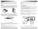
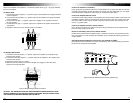
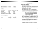
Figure 3: Upright Mount on Horizontal Surface Figure 4: Parallel Mount on Vertical Surface
The amplifier may be mounted upright on a horizontal surface (see Figure 3) or parallel to a
vertical surface (see Figure 4). However, the amplifier should never be mounted upside down
(see Figure 5) for the simple reason that the hot air generated by the amplifier would have to go
through the unit internally on its natural upward path (i.e. "feedback" into the unit) and would result
in increased internal temperature. This would speed up the thermal shut down of the amplifier.
Figure 5: Inverted Mount (Not Recommended)
Vibration: Constant vibration could eventually cause the amplifier to come off its mount, resulting
in stress on wire connections, which, in turn, results in an "open" or "short" circuit. For this rea-
son, a location with minimum vibration and a flat surface for secure and firm mounting should be
chosen for the amplifier.
Moisture: The amplifier should also not be exposed to moisture and water.
Taking all the above into consideration, the best mounting position for the amplifier would be the
floor of the trunk or behind the rear seat back.
WIRING LAYOUT
Once the location of all the components has been determined, plan the best routes for all the
necessary wiring, making sure that the wires are easily accessible without dismounting the vari-
ous components.
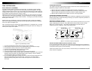
MOUNTING
1. Place the amplifier at the desired location and use it as a template to determine the exact
position of the mounting holes.
2. Mark the mounting holes with a felt pen.
3. Put the amplifier aside.
4. If the mounting surface is carpeted, cut out small circles of the carpet and padding around the
four mounting holes to expose the metal underneath.
5. Use a center punch to ensure drilling the exact position for the screws. DO NOT BEGIN
DRILLING UNTIL YOU HAVE PUT THE AMPLIFIER ASIDE. USING THE AMPLIFIER AS A
DRILLING GUIDE MAY CAUSE IRREPARABLE DAMAGE TO THE AMPLIFIER.
6. Mount the amplifier with the screws provided.
WIRING
Routing audio cables and power cables together would invariably cause radiated engine noise in
your audio system. If possible, run audio cables on one side of your car and power cables on the
other. Never route these wires underneath the vehicle body.
Note: The battery ground should remain DISCONNECTED at all stages of installation.
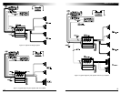
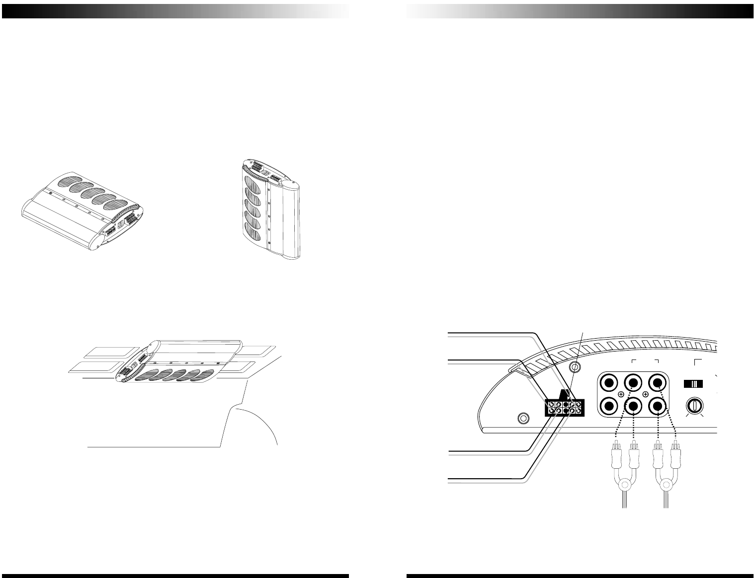
CONNECTION
Connect the front and rear RCA input jacks of the Amplifier to the outputs of the Source Unit (e.g.
radio, cassette player or CD player). If line level output is not available, connect the speaker out-
puts of the source unit to the Loz input of the amplifier.
Figure 6: High/Low Impedance Inputs
Note: Connect the black ground wire to the source unit ground only if alternator noise is present.
8
9
www.coustic.com
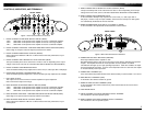
RIGHT REAR(green) +
FRONT
SPKR LEVEL
L
R
SENS
MIN
MAX
MODE
HPF OFF LPF
30
300
60
180
0
+
OUTPUT FRONT REAR
INPUTS
LEFT FRONT(wht/blk) -
LEFT FRONT(white) +
RIGHT FRONT(blu/blk) -
RIGHT FRONT(blue) +
LEFT REAR(yel/blk) -
LEFT REAR(yellow) +
RIGHT REAR(grn/blk) -
GROUND (black)