


Remote Turn-On
In order for the amplifier to turn on, a remote turn-on wire must be connected to a
switched 12 volt source. Typically, the source unit provides a power antenna
(remote) turn on lead which will turn on the amplifier when the source unit is activat-
ed. If this is unavailable, or if voltage drops below 7 volts, a switched 12 volt source
must be used (Refer to page 9, Central Muting and the ACM-420).
Run a wire from the amplifer location through the vehicle to the switched 12 volt
source. Observe the same precautions for routing this cable that you followed for
running the power cable. Cut off excess wire and, using wire strippers, strip the wire
1/4 inch.
Four channel ArtSeries amplifiers are shipped with two speaker connectors. One will
accommodate five wires, and one will accommodate four wires. Locate the five wire
connector which we will refer to as the speaker / remote turn-on connector. On the
underside of the connector are five slotted screws. Loosed the middle screw before
attempting to insert the remote turn-on lead into the end of the connetor. After the
wire is inserted, secure it by the tightening the associated screw. If inserting larger gauge
wire presents a problem, tinning the wire with solder may help. Be sure the connec-
tion is tight. You are now ready to connect the speakers (Refer to Figure D).
Speaker Connection
Fun the speaker wires from the amplifier locations, through the vehicle to the speak-
ers. Observe the same precautions for routing these wires that you followed for run-
ning the power and remote turn-on cables. It is important to use 16 gauge or larger
wire, for proper signal transfer. Cut off excess and, using wire strippers, strip 1/4
inch. Once again, locate the speaer / remote turn-on connector. Loosen the four
remaining screws on the underside of the connector. Insert the speaker leads, one at
a time, into the end of the connector. Check to make sure you've maintained proper
polarity before securing each wire. If inserting larger gauge wire presents a problem,
tinning the wire with solder may help. Be sure the connection is tight. Repeat this
process for the remaining four wire connector on four channel amps. The connectors
may now be plugged into the amplifier (Refer to Figure D).
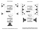
Bridging
All ArtSeries amplifier are capable of being bridged into a mono output due to the
internal design of the amplifier. This feature permits the creation of a mono channel
for a subwoofer or center channel. Also bridging adds flexibility of operation. Any of
the ArtSeries two-channel amplifiers may be used in a one channel (mono), two
channels stereo, or 3 channels - 2 channels stereo and one channel derived mono
configuration. ArtSeries four-channel amplifiers may be used as 2 mono channels, 3
channels - 2 channels stereo and one bridged mono channel, 4 channels - 2 chan-
nel (stereo) front and rear, 5 channels - 4 channels stereo and one derived mono
channel, or 6 channels - 4 channels stereo and 2 derived mono channels.
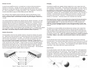
Deriving the mono channel is accomplished by using the left channel positive
wire as the positive speaker wire and the right channel negative wire as the
negative speaker wire. It is important that a minimum of 4 Ohm impedance is
observed. If the impedance drops below 4 ohms while the amplifier is wired in the
mono configuration, the AM II protection circuit will engage the output power will be
reduced.
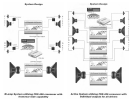
The ability to run stereo satellites wile simultaneously running a mono output from
the same output stage is accomplished simply by running the stereo speakers nor-
mally and tappng into the appropriate wires for teh "Mixed Mono" channel (left chan-
nel positive wire as the positive speaker wire and the right channel negative wire as
the negative speaker wire). Again, for optimum performance, speaker impedance
should be 2 Ohms on the stereo channels and 4 Ohms on the mono channel.
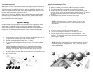
Inputs
On the left side panel of two-channel ArtSeries amplifier are one pair of RCA left
and right inputs. Four-channel models feature two pair of RCA inputs and a "2/4 way"
switch. If both "Input 1" and "Input 2" are to receive the same input signal, place the
"2/4 way" switch in the on (in) position. This will parallel the inputs together internally
in the amp. In this mode, either set of inputs may be used.
Gain Control
On the left end panel, next to the inputs, is the gain control. This control adjusts the
level of the input signal of your source unti. This control requires a small flat-bladed
screwdriver for adjustment. Upon installation of the amplifier, the gain control must
be adjusted. This can be done by first turning the gain all the way down (counter-
clockwise). Turn the volume on the source unit up to two-thirds. Then adjust the gain
control until the desired volume is obtained without audible distortion.