


Tools / Parts Needed for Installation (not supplied):
Small flat blade screwdriver Phillips screwdriver
Wire cutters Wire strippers
Soldering iron Solder
Flux cleaner 5 washers, 4 #6 and 1 #8 sheet metal screws
2 - ring connectors In-line fuse holder and fuse
Speaker wire - 16 gauge or larger Power and Ground wire - 12 gauge or larger
Heatshrink Grommets
Silicone or similar material
Mounting
To prevent damage to the amplifier while driving, mount it in a secure place. Choosing
the appropriate location will depend upon your vehicle and the complexity of your system
design. It may be mounted in any compatible space that is convenient to your needs and
provides sufficient airflow. Adequate ventilation allows the amplifier to dissipate the heat
that develops during operation. Inadequate ventilation may result in overheating. The
thermal protection circuit will engage when the heatsink temperature reaches 75
degrees Celsius. The amplifier will automatically return to normal operation once the
heatsinkcools.
Typical mounting locations include: trunk and passenger compartment (floor or under
seat). Never mount the amplifier in a location, which would subject it to immersion or
exposure to water.
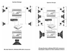
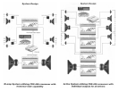
The Art Series' uniquely shaped heatsink is designed for high-efficiency cooling but
improper mounting may compromise its ability to cool. When mounting the amplifier in a
confined space (i.e. under), care must be taken to ensure that at least two inches of
clearance is provided around the amplifier. If the amplifier is located in an area which
has restricted air-flow or is totally enclosed, a fan may be used to improve air circulation.
Power and Ground
Before beginning, disconnect the negative (-) terminal of the battery before working on the
positive terminal to prevent a short to ground. Reconnect the negative terminal only after all
connections have been made.
The Art Series amplifiers are designed to operate from a car's (+) positive 12 volt,
negative ground electrical system. PPI recommends that the power and ground cables
be a minimum of 6 gauge for the A1200, 10 gauge for the A300 & A600 and 12 gauge
for the A100 & A200. Depending upon the complexity of your system, larger gauge wire
may be needed. PPI's Exclusive Wire Connection System will accept up to 6 gauge
cable.
The main power cable should run from the amplifier location, through the vehicle to
the battery, avoiding sharp corners, creases, and sharp body parts. When passing
through any metal wall (i.e. firewall, etc), a grommet must be used to prevent the
wire from chaffing and shorting to ground.
For safety reasons, PPI recommends that the power cable ve fused at the positive
terminal of the battery. If this fuse is not installed, and the power wire shorts to
ground (between the battery and the amplifier), a fire can result. The fuse at the bat-
tery should be of the same value as the chassis fuse located on the right-hand end
panel of the amplifier. Consult your Authorized PPI dealer for an appropriate in-line
fuse holder that meets the needs of your installation. We suggest crimping and sol-
dering all wire connections. Insulate the connection with heat shrink to prevent a
short to ground
The ground wire should be of teh same gauge as the power wire. In systems with
over 800 watts of total output power, the ground and power cables should run paral-
lel to each other to avoid unwanted system noise. As a "rule of thumb", use as short a
length of wire as possible. Locate an area near the amplifier that is metal (the floor is
ideal) and clean an area about the size of a quarter to bare metal. Drill a pilot hole in
the middle of this area. Be Careful!! Inspect the area underneath to be sure you aren't
drilling into wires, brake or fuel lines, etc. Terminate the wire with a ring connector
and attach it to the bare metal using a #8 sheet metal screw and washer (not sup-
plied). We suggest crimping and soldering this connection. Insulate the connection
with heat shrink. It is important that this connection be solid. After the conenction is
complete, coat the area with silicone or some similar material to prevent rust from
developing.
Once you have run both the power and ground wires, it's time to connect the cable to
the amplifier. Be sure that you have not reconnected the ground cable to the nega-
tive post of the battery. Cut off excess wire and, using wire strippers, strip the power
and ground cables 1/4 inch. Locate the power and ground connector (supplied). On
the under side of the connector are two slotted screws. With a small flat bladed
screw driver, loosen these screws before attempting to insert the cables. After you
have inserted the bared end of each cable into the connector, secure it by tightening
the associated screw. If inserting larger gauge wire presents a problem, tinning the
wire with solder may help. Be sure each connection is tight. Once the wires are
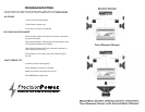
secure, the connetor may be plugged into the amplifier. Please Note: the power /
ground connector is keyed to a slot in the end panel and can only be inserted one
way - with the head of the fastening screws pointing down. (Refer to Figure C.)