


© 2007, The Chamberlain Group, Inc.
01-17468D All Rights Reserved
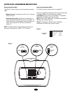
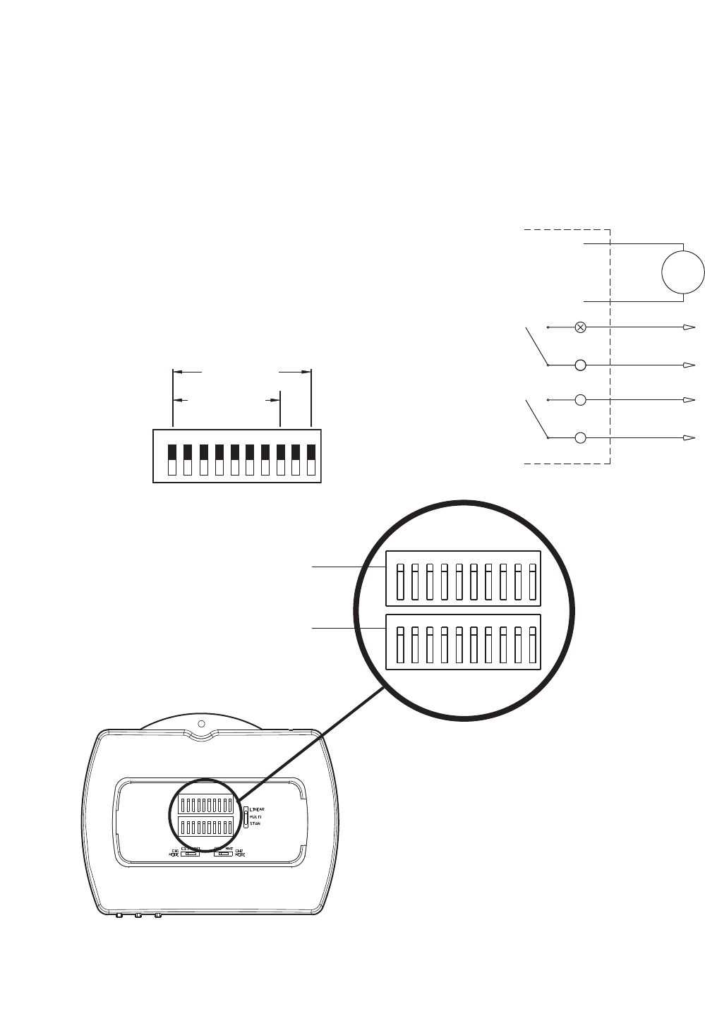
Setting DIP Switch
The TriCode
®
Receiver DIP switch CH1 is factory set OFF (1-10)
and CH2 is factory set ON (1-10).
Locate the 10 position DIP switch. If this is a new installation
using TriCode
®
transmitters, randomly set switches matching
those of the transmitter. Never use factory settings. If receiver is
used with Linear/Delta 3
TM
, Multi-Code
TM
or Stanley
TM
transmitters,
match the receiver DIP switch to the above transmitters. Some
transmitters may use toggle switches and it may be difficult to
determine on & off. If so, try reversing the setting on the
TriCode
®
DIP switch (Figures 4 and 5).
NOTE: In 'LINEAR/DELTA-3
TM
' mode (8-bits system) the last 2
bits (DIP #9 & 10) settings are ignored. They can be left in either
‘ON’ or ‘OFF’ settings.
Figure 4
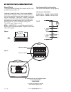
DIP SWITCH SETTINGS & POWER CONNECTIONS
Multi/ Stanley
(1 Thru 10)
Linear/ Delta-3
(1 Thru 8)
1 2 3 4 5 6 7 8 9 10
O
N
O
F
F
TM
TM
DIP
Switch
For installation and service information please
call our toll free number:
1-800-528-2806
or contact us through the web at
www.chamberlaingroup.com
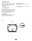
Power Supply and Relay out Connections
There are six wires exiting the housing (Figure 6):
RED & BLACK - POWER INPUT
BROWN & BLUE - CHANNEL 1 RELAY OUTPUT
WHITE & GREEN - CHANNEL 2 RELAY OUTPUT
Figure 6
DIP
Switches
Channel 2 DIP Switch
Channel 1 DIP Switch
12345678910
O
N
1234 5 6 78910
O
N
1234 5 6 789 10
O
N
12345678910
O
N
Figure 5
Relay
Output
Ch1
Relay
Output
Ch2
Red
Black
Brown
Blue
White
Green
Power
Supply
12V/24V