


2
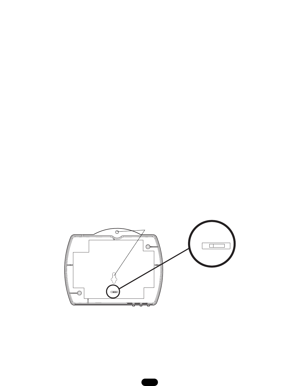
POWER SWITCH SETTINGS
P3
24V 12V
JUMPER
(P3)
Back View
24V 12V
P3
Mounting Holes
Figure 1
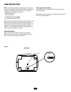
Power Supply Selection Setting
The TriCode
®
receiver is factory set for 24 volt power input if
12 volt is required.
Remove back cover of receiver by removing screws. Set jumper
to the 12 volt setting (Figure 1).
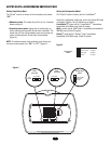
NOTE: To avoid the possibility of duplicating codes in adjacent
systems, all transmitters and receivers should be re-coded prior
to operation. Unless using maximum number of codes the
following four codes should not be used:
· All DIP Switches ON
· All DIP Switches OFF
· DIP Switches alternating ON/OFF
· DIP Switches alternating OFF/ON
Receivers should be installed at least 5' apart to avoid cross-talk.
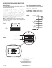
After completing installation, operate transmitter outside of
building to make certain the chosen DIP switch setting does not
operate with nearby garage door operators and/or security
systems. If so, select another DIP switch setting and check the
coded signal again. Repeat as necessary.
RECEIVER MOUNTING
Mount receiver to wall using #6 hardware (not provided).
Hardware used will depend on mounting application. Refer to
Figure 1 for receiver mounting hole locations.