


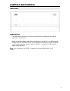


CONTROLS AND DISPLAYS
Do not connect the outputs of the SA-500.1 to the outputs of other amplifiers or to a
speaker switchbox or volume control with a common ground. If you are unsure, check
with Cary Audio or the manufacturer of the device. Failure to follow this can damage
your amplifier and void its warranty.
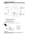
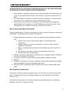
3. FUSE HOLDER
Use only 8A (120v) or 4A (240v)
4. AC POWER CONNECTOR/ MAIN POWER SWITCH
Connect to AC mains using the included power supply cord. Turn the main power switch on
before use.
5. REMOTE TRIGGER INPUT
Enables the SA-500.1 to be controlled by an external device with a 3.3V DC minimum to
24V DC maximum trigger output. Connect the trigger output of the external device to the
TRIGGER INPUT of the SA-500.1 power amplifier. The SA-500.1 will automatically respond
when the external device is powered on and off. When the controlling device is turned on,
the amplifier will turn on after a delay. This delay is intentional and serves to protect the
speakers while the unit stabilizes. During start-up, you may hear a relay clicking. This is
normal.
6. SPEAKER OUTPUT CONNECTORS
Provide audio output for the speakers. Output connectors can accept bare speaker wires or
most spade and banana connectors. When using bare speaker wires, loosen the connector,
insert the wire into the receptacle, and tighten the connector. The same procedure should
be used for spade connectors.
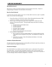
CONNECTING TO A SUBWOOFER
The subwoofer should be connected to the preamplifier or processor through its low level inputs.
Do not under any circumstances connect the amplifier to a subwoofer through its high
level (speaker) inputs. There is a potential of damaging the amplifier using this type
of connection due to differences in grounding schemes used by some subwoofer
manufacturers.
Failing to observe the following precaution will void your warranty.
10