


Front Panel Features
AC-ON ROTARY SWITCH: Turns AC power on in the “on” position.
GREEN ‘CAT EYES’: Indicate audio power output, fully closed eye at maximum power.
Rear Apron Features
INPUT: Signal input connection via either RCA or XLR shielded interconnect cables. Pin
#1 is the shield, #2 positive phase signal on XLR connector.
INPUT SWITCH: Push in direction of the type of input to be utilized, RCA or XLR.
OUTPUT: The 5-way speaker binding posts provide the output to the speaker system.
Red posts = positive connections, Black posts = negative connections.
AC: 3 conductor detachable power cord
AC POWER FUSE: Use only a 3 Amp, 250 V ‘slow blow’ fuse.
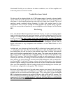
Rocket 88 R Top Panel
BIAS LED: These indicators will light when there is the proper bias voltage operating for
the EL-84 current source tubes along with the proper DC grid bias voltage for the final
output tubes. If these LED’s fail to light, discontinue use and place a call to the Cary
Audio service advisor.
TRIODE/UL SWITCH: These switches change the operation of the Rocket 88 R between
triode, class A, to Ultra-Linear, class A/B. These two switches maybe switched during
operation. If one channel switch is in the opposite position from the other a channel
imbalance will occur. There is 1 dB more gain in the Ultra-Linear position.
BIAS: This screw driver adjustment is used to set the proper DC bias current for the
KT-88 output tubes. REMEMBER, THIS ADJUSTMENT MUST BE ADJUSTED WITH A
METER READING DC mA CURRENT!
TUBE FUSE: This is a ‘fast blow’ _ amp fuse to protect the Rocket 88 R amplifier should
an output tube fail.
CAUTION
USE OF ANY OTHER PROTECTION FUSE CAN DAMAGE UNIT
BIAS JACK: This _” two conductor jack is used to plug in the supplied meter cable. This
is a shorting jack. In other words, when the plug is removed the circuit is automatically