


OPERATION
Your new CAD 120S MKII power amplifier is ready for operation after the speaker,
interconnect cables and the vacuum tubes have been installed into their proper sockets.
Refer to the labeling on the chassis for placement and proper tube installation.
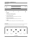
SPEAKER BINDING POSTS
The CAD 120S MKII will drive loudspeaker loads from as low as 2 ohms to a high of 16
ohms without any adjustment. Please remember to keep the proper phase on each
channel when connecting the loudspeaker cables. Red is positive and black is the
negative lead.
TRIODE OR ULTRA-LINEAR MODE SWITCH
The push button located on the lower right side of the front panel will toggle from triode
to ultra-linear modes. There is a blue LED indicator lamp located above the switch.
When this blue LED is illuminated the CAD 120S MKII is in the triode mode. Push the
button again and the red LED will appear. The CAD 120S MKII is now in the ultra-
linear mode. This mode selector system has a memory feature. The amplifier can be
powered down (turned off) and the amplifier operating mode will remain in the last
position. The absolute default mode is triode if the amplifier is unplugged from the AC
wall outlet.
POWER ON / OFF SWITCH
The front panel push button located to the lower left is a power on power off selector.
With the CAD 120S MKII plugged into the wall AC outlet this button will engage the
soft-start system and bring the amplifier to the full operate mode. You will notice that
the two DC current meters on the front panel will light up blue. The vacuum tubes will
light as well. To power down (turn off) simply push the power button once again and the
soft start system will remove the main AC power from the power supply in the CAD
120S MKII.
BIAS MEASUREMENT AND ADJUSTMENT
Setting the operating bias levels on the CAD 120S MKII is a rather simple matter thanks
to the built in front panel DC current meters. These two meters indicate the DC current
being drawn by each channel. The meter to the left reflects the operating current for the
left channel. The corresponding meter to the right indicates the operating bias level of
the right channel. From the factory the bias has been set to approximately 140 ma. DC
current on each channel. This read out will vary with different AC wall voltages.
9