


SA-441-17 Installation and Operating Instructions Page 9 of 15
07/29/08 CP5008A
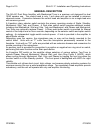
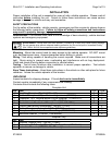
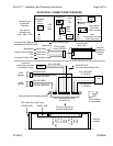
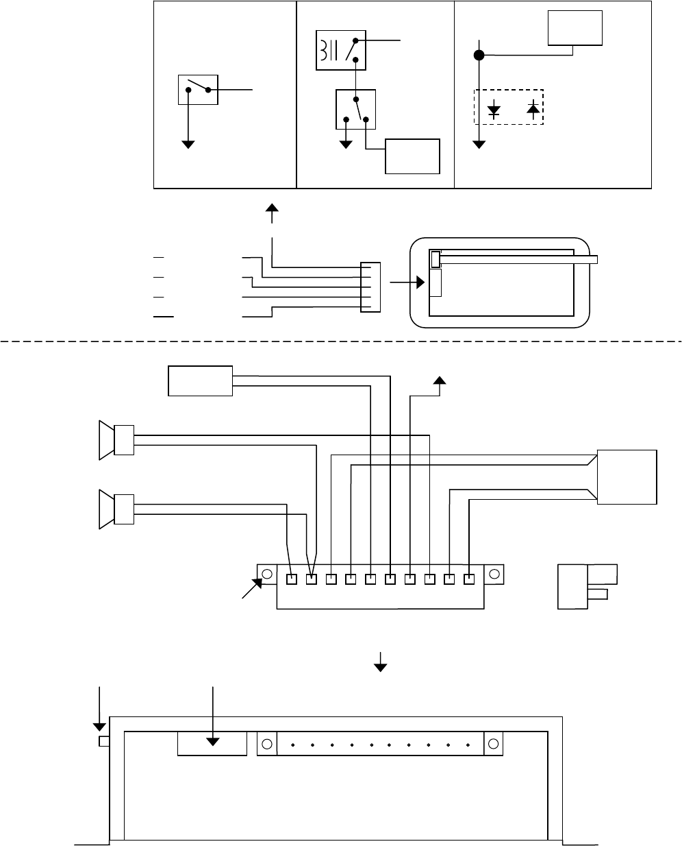
ELECTRICAL CONNECTIONS CONTINUED
Plug into unit first for
terminal identification
Plug secured with mounting screws
10-P Terminal Block Plug
(
CP4833-10
)
SPKR B AMP
Plug installed
this orientation
+
-
+
-
#18 AWG BRN/BLK
#18 AWG BRN
+
-
BAT
#14 AWG BLK
(2 LEADS)
#14 AWG RED
(2 LEADS)
#18 AWG ORG/BLK
#18 AWG ORG
RADIO
100W
S
p
eaker
100W
S
p
eaker
#22 AWG BLU
SPKR
A
Æ
SPK COMÆ
POSÆ
POSÆ
RADÆ
RADÆ
CTRLÆ
SPKR BÆ
NEGÆ
NEGÆ
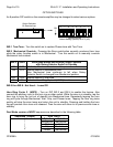
Control Head
Rear View
Optional
Microphone
Extension
Cable
Auxiliary Input
Connection
Examples
Aux input is
activated with
+VDC AND -VDC
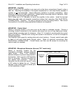
Remote
A
m
p
lifier
HORN RLY
+VDC
or
-VDC
Added
SPDT
Switch
To
A
UX
Vehicle
Horn
Horn
Circuit
Note:
Vehicle horn will also
sound with siren
May need to
add diode
(10mA current)
To
A
UX
Vehicle
Horn
S
p
lice
or
+VDC
or
-VDC
Momentary
SPST
Switch
To
A
UX
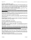
Connect to
output jack, terminals
or speaker of radio
#22 AWG WHT
To Control Head White Wire
Red Wire
Black Wire
White Wire
Yellow Wire
Control Head
Cable (CP3040)
Green Wire
Backlighting
Control Line to Amplifie
r
-VDC
Customer Fused +VDC
Control Head Cable may be
extended with #22AWG Wire
15A Automotive T
y
p
e Fuses
(AUX) Auxiliary Input
SPKR A AMP