


A (L)
B (R)
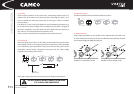
VORTEX
Z ≥ *Z
min
Z ≥ *Z
min
VORTEX
A
B
Z
res
≥ 0,5*Z
min
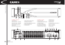
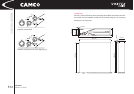
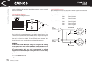
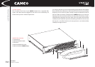
Input
Ground
Lift
Input Ground Lift in
position: grounded
LINK BInput
Channel B
2
3
1
1
3
22
3
1
To
Channel B
To
Channel A
Input
Channel A
LINK A
3
1
2
3 INSTALLATION
USER MANUAL
VORTEX 6, 4, 2.6 and 200V
P.14
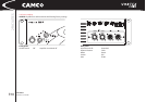
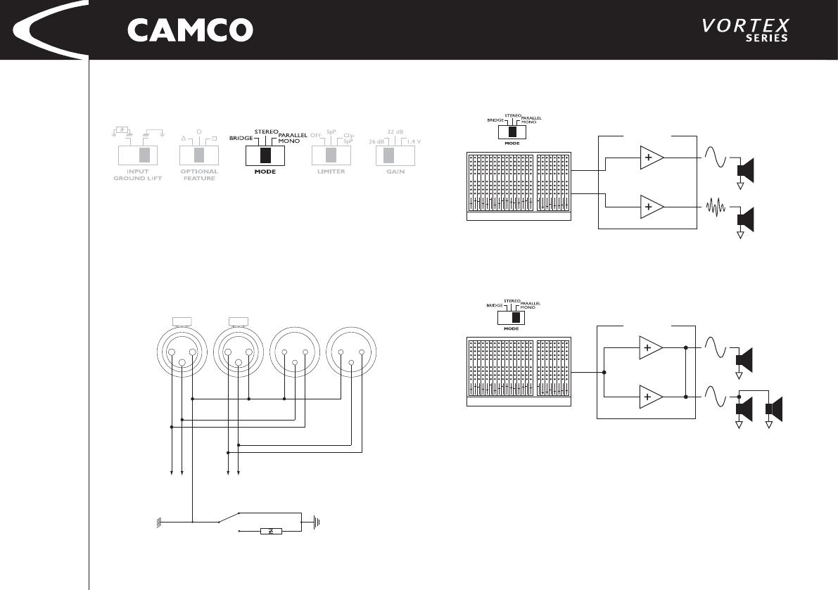
3.8 Mode Selector
The switch on the rear panel changes the operating mode. Moving this switch
will shutdown the amplifi er and restart it in the new operating mode.
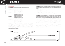
3.9 Wiring
3.9.1 E.U.I. and XLR Connection
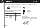
XLR: Pin 1 = Ground (or lifted via 15 Ω resistor)
Pin 2 = Hot (inphase)
Pin 3 = Cold (out of phase)
Always use symmetrical (balanced) shielded cable to connect the amplifi er.
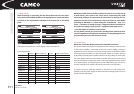
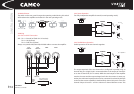
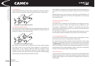
3.9.2 Stereo Operation
Two fully independent amplifi er channels (normal operating mode).
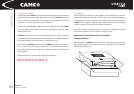
3.9.3 Parallel-Mono Operation
Parallel operation of the two channels together.
The output terminals of the two channels are confi gured in parallel using an
internal relay. The (single) load is connected either to the output of channel A
or to that of channel B (as if in stereo). While the total output of the amplifi er
remains the same and the output voltage level is also the same as in stereo op-
eration, the minimum impedance that can be connected is reduced by half due
to the fact that current capability is doubled. Only channel A-Input is active. The
channel B-Input is inactive – turn the volume on channel B down to zero. This