


740Aazur
5
ENGLISH
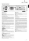
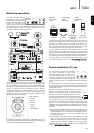
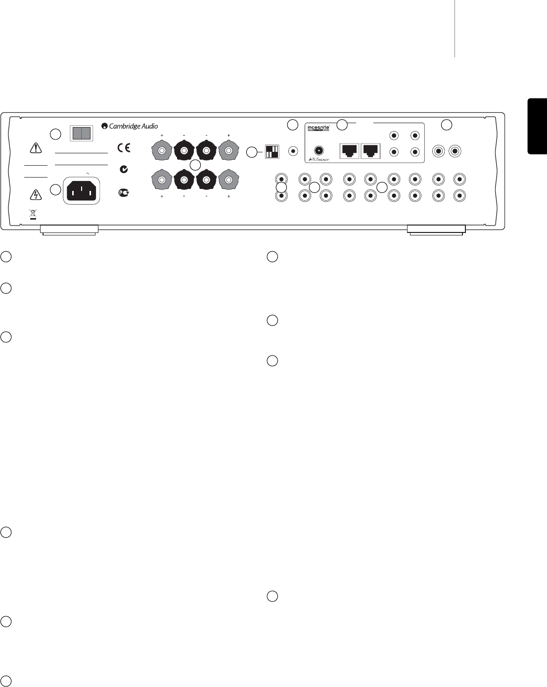
Rear panel connections
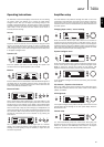
Power On/Off
Switches the unit on and off.
AC power socket
Once you have completed all connections to the amplifier, plug the AC
power cable into an appropriate mains socket then switch on. Your
amplifier is now ready for use.
Loudspeaker terminals
Two sets of loudspeaker terminals are available, A (main loudspeaker
terminals) and B (secondary loudspeaker terminals). Both sets of
speakers can be turned on and off independently. Connect the wires
from your left channel loudspeaker to the LEFT + & - terminals, and the
wires from the right channel loudspeaker to the RIGHT + & - terminals.
In each case, the red terminal is the positive output and the black
terminal is the negative output.
Care should be taken to ensure no stray strands of wire short the
speaker outputs together. Please ensure that the loudspeaker terminals
have been tightened completely to provide a good electrical connection.
It is possible for the sound quality to be affected if the screw terminals
are loose.
Note: When using one pair of speakers, use speakers with a nominal
impedance of between 4-8 ohms. When using two pairs of speakers,
use speakers with a nominal impedance of between 6-8 ohms. Please
also note that when multiple speakers are connected across the
amplifier’s outputs, the load (as seen by the amplifier) is reduced. This
will make the amplifier work harder, and hotter!
Dip-switches
Used in conjunction with custom installation (C.I.) systems. Refer to the
‘Custom installation’ section for more information.
Front Panel IR - Set to ‘On’ for normal operation.
Control Bus Passthru - Turns on/off looping of Control Bus signals from
Input to Output.
Reserved - Not used.
IR (Infrared) Emitter In
Allows modulated IR commands from multi-room systems to be received
by the amplifier. Commands received here are not looped out of the
Control Bus. Refer to the ‘Custom installation’ section for more
information.
A-BUS™ Ready / Incognito Ready™
multi-room outputs
PSU - Connect an Incognito PS5 to supply power to the connected multi-
room keypads/speakers.
Keypad 1/2 - Connect one or two Incognito A-BUS KP10 keypads (or
other A-BUS compatible keypads) using CAT5/5e cable. Incognito AS10
Active Ceiling Speakers can also be connected here.
IR - Four IR outputs for remote control of source equipment.
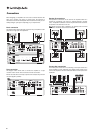
Please refer to the ‘Multi-Room’ section of this manual for more
information on connections and set-ups.
Control Bus
In - Allows un-modulated commands from multi-rooms systems or other
components to be received by the unit.
Out - Loop out for control bus commands to another unit. Also allows the
740A to control some Cambridge Audio units.
Pre Out
Connect these sockets to the inputs on an external power amplifier(s) or
active subwoofers etc.
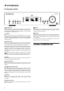
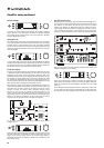
Tape/Rec In/Out
Connect to a tape deck or to the analog output sockets on a MiniDisc,
portable digital music player or CD recorder using an interconnect cable
from the recorder's Line Out sockets to the amplifier's Tape In sockets.
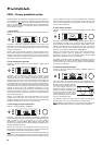
The Tape Input circuit of the 740A is a "monitor" type, different from the
other 7 inputs. For the 7 normal inputs, the source selected for listening
to will be sent out of the Tape Out for recording. The source currently
being listened to and (optionally) recorded is then shown on the front
panel display.
However, when the Tape Input is selected a solid circle will appear
beside TAPE MON indicating that the Tape Input is now being listened to
with a different source being sent out of the Tape Out for recording. The
recording source is also shown by a solid circle by the selected input and
can be changed by pressing the other source buttons. To switch Tape
Monitor off, simply press the Tape Mon input select button again,
toggling this function off.
This feature is most useful when using 3-head analog cassette decks
which allow the signal being recorded to be played back live off tape (via
a 3rd head) whilst it is simultaneously recorded. It is then possible by
toggling the Tape Monitor input on and off to compare directly in real
time the original and recorded signal so that adjustments to the
recording parameters of the tape machine can be made (consult the
manual of your 3-head analog cassette deck for full details).
Inputs 1-5
These inputs are suitable for any 'line level' source equipment such as
CD players, DAB or FM/AM tuners etc.
Note: These inputs are for analog audio signals only. They should not be
connected to the digital output of a CD player or any other digital device.
IR1
IR2 IR4
IR3
Keypad 1 Keypad 2
Pre Out Tape/Rec In
(Input 6)
Tape/Rec Out 2 Tape/Rec Out 1 Input 5 Input 4 Input 3 Input 2 Input 1
Pre Out
Tape/Rec In
Tape/Rec Out 2
Tape/Rec Out 1
Input 5Input 4
Input 3
Input 2
Input 1
Right
Left
Right
Left
Power AC
Off
Power
In Out
Control Bus
IR Emitter
In
PSU
In
On
Multi-Room
International Patent Pending LeisureTech Electronics Pty Ltd
N1863
Caution
Risk of electric shock.
Do not open.
Avis
Risque de choc electrique.
Ne pas ouvrir.
Achtung
Vorm öffnen des gerätes.
Netzstecker ziehen.
azur 740A Integrated Amplifier
Power Rating: 230V AC ~ 50Hz
Max Power Consumption: 750W
Off
On
Control Bus PassThru
Front Panel IR
Reserved
Reserved
www.cambridge-audio.com
AЯ
46
Impedance 4 - 8 ohms one pair, 6 - 8 ohms per pair if two pairs
Loudspeaker Terminals
Important
Please ensure that loudspeaker terminals are fully tightened
Veuillez s'assurer que les bornes de l'enceinte sont entièrement serrées
B
A
Designed in London, England
RightLeft
Right
Left
B
A
Manufactured in an ISO9002 approved facility
This device complies with part 15 of
the FCC Rules. Operation is subject to the
following two conditions: 1) This device may
not cause harmful interference; 2) This device
must accept any interference, including
interference that may cause undesired operation.
1
1
2
3
4
65
8 10
2
3
7
5
6
7
8
10
4
9
9