


650Razur
7
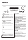
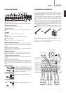
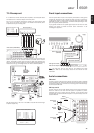
Rear panel connections
Service/Normal
For dealer use only - Switches the 650R between normal (default) mode and
two Service modes. Do not
change the mode to service or make RS232
connections to it in service mode as damage may result!
RS232C
Used for control of the 650R in Custom Install situations. A full protocol is
available for the 650R on our website.
FM/AM antenna
All tuner antenna connections are made here. Refer to the ‘Antenna
Connections’ section of this manual for more information.
HDMI
Inputs and output to a suitable TV/Monitor. The HDMI inputs can be assigned
in the OSD to the BD/DVD, Video 1, Video 2 or Rec 1 sources, see later
section.
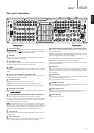
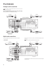
Video 1/2, Recorder 1/2, BD/DVD, Aux
Please refer to the connection diagrams later in this manual for more
information on these inputs and outputs.
TV/Mon outputs
S-Video - Connect to your television via S-Video cable.
Composite - Connect to your television via 75 ohm RCA phono cable.
Component - Connect to the Cr/Pr, Cb/Pb, & Y terminals of a television set.
Heat tunnel vent grille
Allows cooling of internal circuitry via the 650R’s proprietary X-TRACT heat
tunnel. DO NOT OBSTRUCT!
Component Video inputs (BD/DVD, Video 1/2, Recorder 1)
Connect the Component Video outputs from the source equipment.
The Video 1/2 input can be used for either source simply by selecting HDMI
for either source using the Video Input Type button or doing the same thing
via the Video Input Type menu in the OSD.
Note: The preferred connection method for video inputs or outputs is always
Composite Video, then S-Video, then Component Video, then HDMI in
ascending order of quality (HDMI being the highest quality). HDMI and
Component Video sources often also support Progressive Scan which gives
better picture quality if supported by both your BD/DVD player and TV.
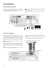
7.1 Direct In
Connect to the output terminals of a DVD-A, SACD player or other 5.1/6.1/7.1
analogue source.
7.1 Preamp Out
Connect to the 5.1/6.1/7.1 channel input terminals of another amplifier
system, separate power amps, subwoofer or active loudspeakers.
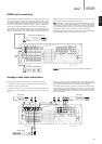
A-BUS™ Ready/Incognito Ready™ multi-room outputs
PSU In - Connect an Incognito PS5 to supply power to the connected multi-
room keypads/speakers.
Keypad 1/2 - Connect one or two Incognito A-BUS KP10 keypads (or other A-
BUS compatible keypads) or AS10 Active Ceiling Speakers using CAT5/5e
cable, allowing 2nd/3rd zone multi-room capability.
IR - Three IR emitter outputs for remote control of source equipment.
Video Out 1/2 - Provides video feeds to the 2nd/3rd zone.
Please refer to the ‘Multi-Room’ section of this manual for more information
on connections and setup.
Emitter In
Allows modulated IR commands from multi-room systems or IR repeater
systems to be received by the 650R. Commands received here are not
looped out of the Control Bus. Refer to the ‘Custom Installation’ section for
more information.
Control Bus
In - Allows un-modulated commands from multi-rooms systems or other
components to be received by the unit.
Out - Loop out for control bus commands to another unit.
Speaker terminals
Connect to loudspeakers with an impedance of between 4-8 ohms. 7.1, 6.1,
5.1 or less connections can be made.
Mains power lead
Once you have completed all connections, plug the AC power lead into an
appropriate mains socket. The AV receiver is now ready for use.
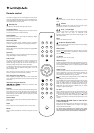
Power On/Off
Switches the unit on and off.
Do not obstruct ventilation / Do not obstruct ventilation /
Ne pas obstruer la ventilationNe pas obstruer la ventilation
Do not obstruct ventilation / Do not obstruct ventilation /
Ventilation nicht verschließenVentilation nicht verschließen
Front
Right
Front
Left
Surround
Left
Surround
Back Left/
Surround Back
Centre
Surround
Right
Surround
Back Right
Made under licence in China
AM 300Ω
Tun er
FM 75Ω
Control
Bus
In
In
Emitter
Out
IR1 IR2
PSU 24V DC In
IR3
12
Keypad 1 Keypad 2
BD/DVD
SR
SBR
SW
L
SL
SBL/SB
Y
Cb/Pb
Cr/Pr
Y
Cb/Pb
Cr/Pr
Y
Cb/Pb
Cr/Pr
Y
Cb/Pb
Cr/Pr
C
7.1 Direct In
L
R
L
R
Serial No. label fitted on underside
R
SR
SBR
L
SL
SBL/SB
CR
TV/Mon Out
Video 1/2 Recorder 1
Speaker Impedance 4-8 Ohms
Multi-
Room
RS232C
In In
InInInIn Out InOut
L
R
Video 2Video 1 Recorder 1 BD/DVD Rec 2 Aux
CD
Rec 2
Composite S-VideoDigital OpticalDigital Co-axial
Composite
S-Video
Digital Optical Digital Co-axial
Video Out
TV/Mon Out
Power AC
Power
On
Off
A-BUS® US Patent # 7,181,023, 6,389,139
EP Patent # 1004222
Service 2
Service 1
Normal
In 3 In 2
In 1
Out
HDMI
7.1 6.1 5.1
SW
Use
approved
PSU only
Max Power Consumption:
1400W
Power Rating:
220-230V AC ~ 50/60Hz
Designed in London, England
azur 650R AV Receiver
www.cambridge-audio.com
This device complies with
part 15 of the FCC Rules.
Operation is subject to the
following two conditions:
1) This device may not cause
harmful interference;
2) This device must accept
any interference, including
interference that may cause
undesired operation.
Manufactured in an ISO9001 approved facility
Component
7.1 Preamp Out
1
1
2
3
4
6
5
8 9 10
11
12
13
14
15
16
2
3
4
5
6
7
14
15
8
9
10
11
12
13
6
7
16
ENGLISH