


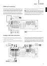
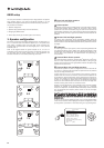
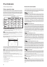

If it is desired to connect external power amplifiers, use Phono/RCA leads
connected to the 7.1 Preamp Outputs on the rear panel.
For 5.1/6.1/7.1 use set the ‘Preamp Out’ setting in the ‘Output Setup’ OSD
menu to 'Pre Out' rather than 'Normal'. This mutes all the internal power
amplifiers as they are not being used.
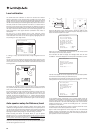
Alternatively the 650R features an External 2-Channel mode. This allows the
650R to reproduce all the surround channels of suitable source material
(Centre, Surrounds and Sub) whilst the Left and Right Front speakers are
driven by an external power amplifier or other amplifier capable of supporting
fixed level inputs (e.g. Cambridge Audio’s own 740A or 840A amplifiers).
Set the ‘Preamp Out’ to ‘Ext 2 Ch’ in the OSD to mute the front left and right
amplifier outputs only:
I
n
PSU24VDCIn
Keypad1
Keypad2
B
D
/
DV
D
S
R
SBR
SW
L
S
L
SBL/SB
Y
Cb/P
b
Cr/Pr
Y
Cb/Pb
Cr/Pr
Y
Cb/P
b
Cr/Pr
Y
Cb/Pb
Cr/Pr
C
7.
1
Dir
ect
I
n
R
SR
SBR
L
SL
SBL/SB
C
R
T
V
/
Mon
O
u
t
Video
1/2
Reco
r
de
r
1
Multi-
Multi
Room
Room
P
owe
r
On
O
ff
O
SW
SW
Max Power
C
onsumption
:
1400
W
P
ower
R
at
i
n
g:
220
-
230
V A
C
~ 5
0
/
60
Hz
7.
1
Pream
p
O
u
t
SR
SBR
L
SL
SBL/SB
C
R
SW
7.1 Preamp Out
Power amplifier/s
Subwoofer
Surround back left
Surround left
Left
Right
Surround right
Surround back right
Centre
Phono cables (2RCA-2RCA)
650Razur
13
Front input connections
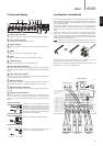
The front panel Video 3 input is for temporary connections to video games
consoles etc. Remove the cap to access the Video 3 inputs, and connect to
a video game console or video camera’s outputs using stereo phono cable
(RCA-RCA) and either (1) Composite or (2) S-Video cable, depending on what
your unit supports (S-Video preferred).
If your games console has an optical digital output this can also be used,
allowing the 650R to decode surround sound information if the
console/game supports it.
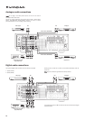
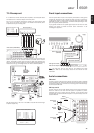
FM aerial
Connect an aerial to the FM 75 ohm socket (a simple wire aerial is supplied
only for temporary use). Extend the lead and move the aerial around until you
get the best reception. For continued use, we strongly recommended using a
75ohm outdoor FM aerial.
AM loop aerial
Connect each end of the single length antenna to the antenna terminals.
Place the antenna as far from the main system as possible to prevent
unwanted noise and to obtain optimum reception. If the AM loop aerial
provided does not receive sufficient reception, it may be necessary to use an
outdoor AM aerial.
Aerial connections
AM 300Ω
Tun er
FM 75Ω
FM aerial
FM external
aerial
AM external
aerial
AM loop
aerial
OR
OR
Ground
(optional)
ENGLISH
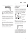
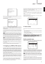
7.1 Preamp out
Audio In/Out Setup Menu
BD/DVD In: HDMI1
Video1 In: HDMI2
Video2 In: HDMI3
Video3 In: Analog
Rec.1 In: Analog
CD In: Analog
Preamp Out : Ext.2 Ch
Return : [OSD]
+
_
+
_
_
Right
Right
Righ
t
Ri
g
ht
+
_
+
L
e
ft
Lef
t
L
e
ft
Le
ft
Righ
t
L
e
f
t
Ri
g
h
t
L
ef
t
IR1
IR
2
IR
3
IR
4
K
eypad
1
K
eypad
2
Multi-Room
Multi
-
Room
IR
E
m
i
tte
r
In I
n
O
u
t
Right
L
e
ft
Ri
g
h
tL
e
f
t
Pream
p
O
u
t
Ta
p
e
O
u
t
T
a
p
e I
n
I
n
p
ut
7
I
n
p
ut
6
In
p
ut
5
In
p
ut
4
In
p
ut
3
In
p
ut
2
In
p
ut
1
Preamp Ou
t
T
ape Ou
t
T
ape
In
I
nput
7
I
nput
6
I
nput
5
Input
4
I
nput
3
Input
2
Input
1
L
ouds
p
eaker Terminal
s
I
m
p
edance
4
-
8
ohm
s
In
p
ut
1
Balanced Audi
o
RS232C
Control Bu
s
Po
w
er
P
SU
In
I
nternat
i
ona
l
P
atent
P
en
di
n
g
L
eisureTech Electronics Pt
y
Ltd
Please ensure that loudspeaker terminals are
f
ully tightened
Veuillez s'assurer que les bornes de l'enceinte sont entièrement serrées
B
B
A
A
G
N
D
www.cam
b
r
idg
e-au
di
o.co
m
M
anufactured in an ISO9002 approved facility
P
ower A
C
D
es
ig
ne
d
i
n
L
on
d
on,
E
n
gl
an
d
C
aution Risk o
f
electric shock. Do not o
p
en
.
A
v
i
s
R
is
q
ue de choc electri
q
ue.
N
e
p
as ouvrir
.
A
c
h
tun
g
Vorm öffnen des gërates.
N
etzstecker ziehen
.
azur 8
4
0A Class XD
™
Integrated Ampli
f
ier
P
ower
R
at
i
n
g
:
230
V A
C
~
50
Hz
M
ax Power
C
onsumptio
n
:
800
W
O
n
O
ff
N1863
AM
300
Ω
Tu
n
er
FM
75
Ω
In
I
n
Out
PSU 24V DC In
Ke
y
pad
1
K
e
y
pad 2
BD
/
DV
D
S
R
SBR
S
W
L
S
L
SBL/SB
Y
C
b
/
Pb
Cr/Pr
Y
C
b
/
Pb
Cr/Pr
Y
C
b
/
Pb
Cr/Pr
Y
C
b
/
Pb
Cr/Pr
C
7.
1
Dir
ect
In
L
R
L
R
R
SR
SBR
L
SL
SBL/SB
C
R
T
V
/
Mon
O
u
t
V
ideo
1/2
Reco
r
de
r
1
Multi
-
Multi
Room
Room
RS232C
In
I
n
In
In
In
In
Out
Out
I
n
Out
L
R
V
i
deo
2
Vi
deo
1
Reco
r
de
r 1
B
D
/
DVD R
ec
2
A
ux
C
DR
ec
2
Composite S-Vide
o
Di
g
ital Optical
D
i
g
ital Co-axial
Composite
Composite
S
-Vi
deo
D
igital
O
ptical
D
igital
C
o-axia
l
TV
/
Mon
O
u
t
P
o
w
e
r A
C
Power
On
Off
O
S
ervice
2
Se
rvi
ce
1
No
rm
al
In
3
In
2
I
n 1
Out
H
DM
I
71
7
.
1
61
6
.
1
51
5
.
1
SW
SW
Use
a
pproved
PS
U only
Max Power Consumption
:
1400
W
P
ower
R
at
i
ng
:
220
-
230
V A
C
~ 5
0/60
Hz
D
es
i
gne
d
i
n
L
on
d
on,
E
ng
l
an
d
a
z
u
r
6
5
0
R AV R
ece
iv
e
r
7.
1
Pream
p
O
ut
Surround
Left
Surround
Right
Surround
Back Left/
Surround Back
Centre
Surround
Back Right
LR
Speaker Impedance 4-8 Ohms
7.1 6.1 5.1
7.1 Preamp Out
SW
+
_
Right
Right
+
_
Left
Left
Right
Left
Input 1
Input 1
Loudspeaker Terminals
Impedance 4 - 8 ohms
A
A
L
SL
Amplifier
(e.g. 840A)
650R
R
SR
C
SBR
Sub
LR
SBL
Audio Video S-Video OpticalVideo 3 L
Auto Setup
R
Video games console/
Video camera outputs
Composite video cable
Stereo phono cable
(RCA-RCA)
S-Video cable
Optical cable (OPT-OPT)
1
2
Note: The Left front input is also used for the supplied auto setup
microphone. Refer to the ‘Auto setup’ section of this manual for more
information.
Audio In/Out Setup Menu
BD/DVD In: HDMI1
Video1 In: HDMI2
Video2 In: HDMI3
Video3 In: Analog
Rec.1 In: Analog
CD In: Analog
Preamp Out : Ext.2 Ch
Return : [OSD]