


340Razur
5
ENGLISH
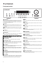
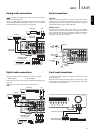
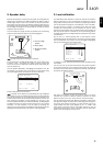
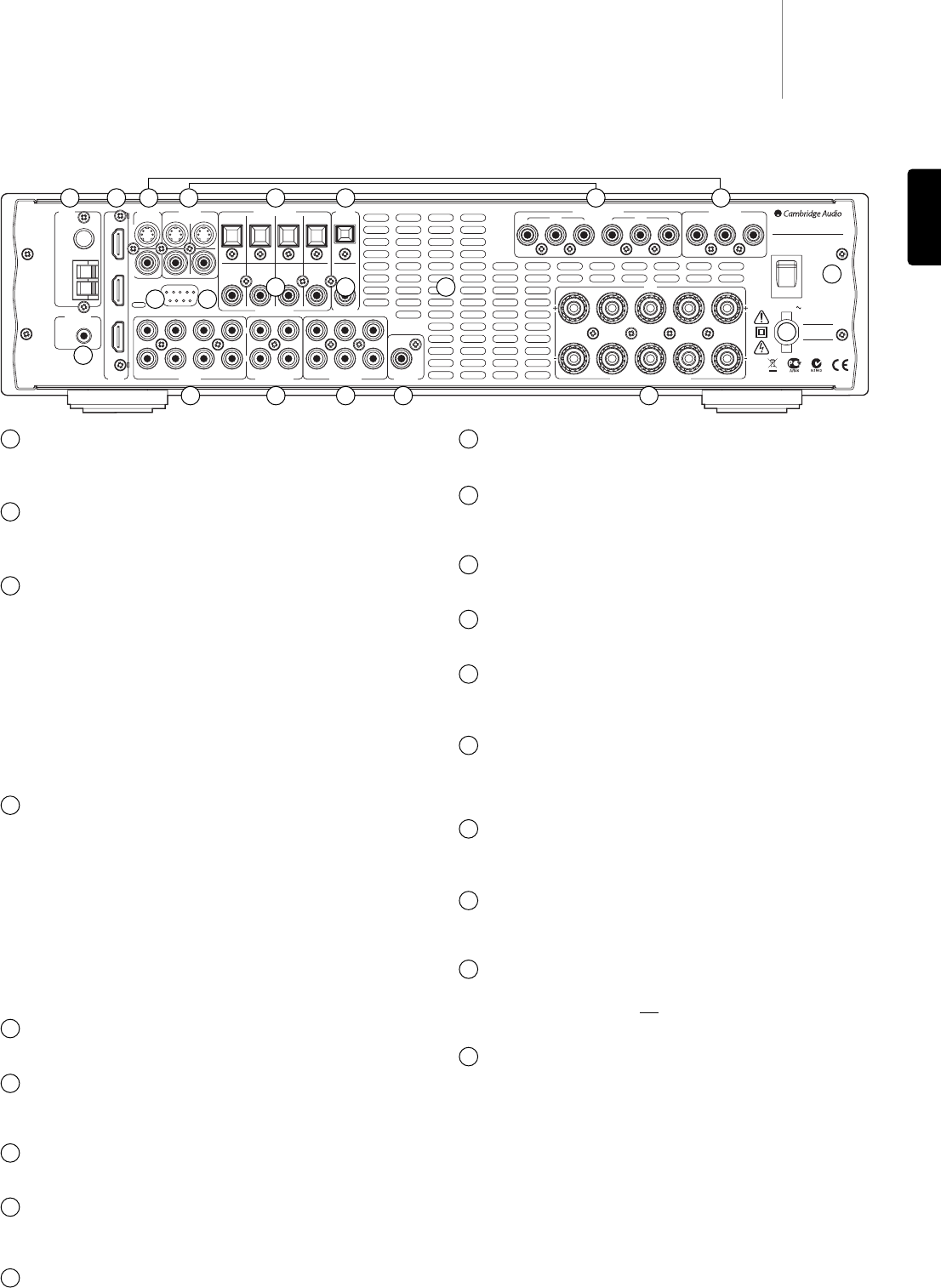
Power On/Off
Switches the unit on and off.
Mains power lead
Once you have completed all connections, plug the AC power lead into
an appropriate mains socket. The AV receiver is now ready for use.
Speaker terminals
Connect to loudspeakers with an impedance of between 4-8 ohms.
Subwoofer Output
Connect to a powered (active) subwoofer.
5.1 Direct In
Connect to the 5.1 channel output terminals of a DVD player with built-
in multi-channel decoding for playing DVD-A or SACD.
Tape/MD/CDR
Connect the Tape Play sockets to the line output terminals of a Tape
deck, MD player, CD-R etc. Connect the Tape Rec sockets to the line
input terminals of a Tape deck, MD player, CD-R etc.
Audio inputs
Connect to the audio line output terminals of a source device (eg CD,
DVD player etc).
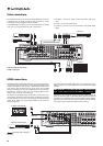
RS232C
For use by an installer/dealer for software updates, or for control of the
340R by Custom Install (C.I.) systems.
Update/Normal
For dealer use only - Switches the 340R between Normal (default) mode
and Software Update mode. Do not change the mode to Update or make
connections to it in Update mode as damage may result!
IR Emitter In
Allows modulated IR commands from multi-room systems or IR repeater
systems to be received by the 340R.
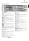
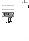
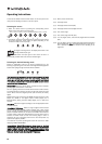
Rear panel connections
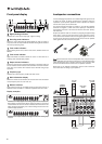
FM/AM antenna
All tuner antenna connections are made here. Refer to the ‘Aerial
connections’ section of this manual for more information.
HDMI
Inputs and output to a suitable TV/Monitor. The HDMI inputs can be
assigned in the OSD to the DVD, Video 1, or Video 2 sources (see later
section of this manual for more information).
TV/Mon outputs
S-Video - Connect to your television via S-Video cable to display the
picture of any S-Video connected unit.
Composite - Connect to your television via 75 ohm RCA phono cable to
display the picture of any composite video connected unit.
These outputs are also used to view the 340R’s on-screen setup menu.
Component - Connect to the Cr/Pr, Cb/Pb, & Y terminals of a television
set.
Note: There is no On-Screen Display setup menu present on the
Component Video output.
Video inputs
S-Video - Connect to the S-Video outputs from the source equipment.
Composite - Connect to the Composite Video outputs from the source
equipment.
Component - Connect the Component Video outputs from the source
equipment.
Note: The preferred connection method for video sources is always
HDMI (highest quality) then Component Video then S-Video then
Composite Video. HDMI and DVD Component also support Progressive
Scan which gives better picture quality if supported by both your DVD
player and TV.
Digital Optical Inputs
Connect to the digital optical (Toslink) outputs of source equipment.
Optical Out
Connect to the digital optical (Toslink) input of an external recording
device (eg MD/CDR etc) to record from the selected digital audio source.
Digital Coax Inputs
Connect to the digital coaxial (SPDIF) outputs of source equipment.
Coax Out
Connect to the digital coaxial (SPDIF) input of an external recording
device (eg MD/CDR etc) to record from the selected digital audio source.
Heat tunnel vent grille
Allows cooling of internal circuitry. DO NOT OBSTRUCT!
1
11
12
13
14
15
16
17
18
19
2
3
4
9
5
6
7
8
FM
75Ω
AM
Loop
300Ω
Video 1 Video 2 DVD
Sur
Left
Sur
Right
Front
Right
Front
Left
Centre
In OutCD/Aux
CD Video 1 Video 2 DVD
CD Video 1 Video 2 DVD
SW
C
SRR
SLL
Power AC
5.1 Direct In
Cr/Pr Cb/Pb Y Cr/Pr Cb/Pb Y
Cr/Pr Cb/Pb Y
Component Video In
In 1 In 2
Tun er Digital Optical In
Audio In Tape/MD/CDR
L
R
Digital Coax In Coax Out
Optical
Out
TV/Mon Out
Designed in London, England
TV/Mon
Out
www.cambridge-audio.com
azur 340R AV Receiver
Max Power Consumption: 400W
Power Rating: 230V AC ~ 50Hz
Speaker Impedance 4-8 Ohms
5.1
Power
On
Off
In 2In 1
Out
HDMI
Do not obstruct ventilation. Ne pas obstruer la ventilation. Ventilation nicht verschließen.
Component Video
(Assignable)
(Assignable)
Video In
In 1 (Assignable) In 2
S-VideoComposite
This device complies
with part 15 of the
FCC Rules.
Operation is subject
to the following two
conditions:
1) This device may
not cause harmful
interference;
2) This device must
accept any
interference,
including
interference that
may cause
undesired operation.
Subwoofer
Out
Manufactured in an
ISO9002 approved facility
Serial No. label fitted on underside
RS232C
Update
Normal
Caution:
Risk of electric shock.
Do not open.
Avis:
Risque de choc electrique.
Ne pas ouvrir.
Achtung:
Vorm öffnen des gerätes.
Netzstecker ziehen.
In
IR Emitter
1 2 3 4 5
7 8 9
6 4 3
19
10
11
121315 1416
18
10
17