BP16 PREAMPLIFIER
2
Mode (from Analog Mode). Similarly, when
re-entering Analog Mode from Digital Mode
the previously selected analog input will be
automatically re-selected.
See also the DIGITAL-to-ANALOG
CONVERTER OPTION section for more
information.
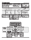
HEADPHONE JACK:
There is a quarter inch headphone output jack
available on the front panel of the Bryston BP16
Preamplifier. Inserting the headphone jack mutes
PREAMP OUT automatically. You can adjust the volume
setting of the headphones by using the volume con-
trol on the front of the BP16 Preamplifier. You may
also utilize the remote control unit to adjust head-
phone volume. The headphones cannot be muted
with the remote control unit or the front panel Mute.
Only headphones with impedances of greater than 50
ohms should be used.
AUXILIARY IR INPUT:
This mono 1/8” (3mm) phone jack allows a direct
connection to equipment whose remote control sys-
tem provides an output from their infra-red LED drive
circuit. The signal connected to this jack, which is
expected to be a 5 volt logic level, should be ≥2.5Vdc
and ≤10Vdc. The tip of the phone jack is positive (+)
and the ring is negative (-).
LED STATUS INDICATORS:
CLIPPING: This LED (light emitting diode) will flash
RED when the output waveform is clipped
thus indicating an overload condition.
MUTE: Lights RED to indicate the outputs are
muted..
POWER: GREEN indicates normal operation
RED indicates Standby
Blinking RED/GREEN a fault or thermal
overload problem in the unit.
ANALOG4Aux2 / DIGITAL4Select:
In BP16-DA models: when this LED is
illuminated green concurrently with either
D1, D2, D3 or D4 LEDs, it indicates that the
digital inputs d1 (SPDIF), d2 (SPDIF), d3
(TOSLINK) or d4 (TOSLINK) have been
selected.
In BP16 & BP16-P models: when illumi-
nated green this LED indicates that the line
level analog audio input AUX-2 has been
selected.
AUX1, CD, TUNER, TV/SAT VIDEO & RECORD:
One of these input source LEDs will light
green to Indicate the active input. In digital
mode these LEDs will light RED if the bit
stream is either absent or unacceptable.
BALANCE When the left/right signal balance is being
shifted one of these LEDs will light to indi-
cate which channel is being attenuated.
Balance can be adjusted in 1dB incre-
ments to up to -6dB in either direction.
Stepping past -6dB in either direction will
mute that channel fully and the LED for
that channel will turn red.
When both LEDs are on (red), PASS
THROUGH mode is indicated. (See “Pass
Through Mode” on page 4)
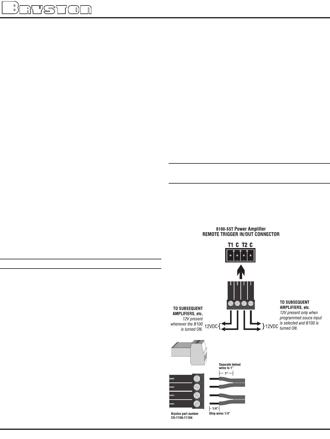
REMOTE POWER CONTROL ~ 12 VOLT
TRIGGER CONNECTOR:
Two trigger outputs are provided. A 12Vdc signal is
placed across the T1 and C pins (either “C” pin can
be used) of the 12V TRIGGERS connector whenever
the unit is fully powered up. When the unit goes into
standby this voltage is removed.
A 12Vdc signal will be
placed across the other
pair of 12V TRIGGER out-
put pins (T2 and either
“C” pin) whenever a cer-
tain user programmed
input is selected as
the source input (see
below for programming
instructions). When any
other input source is


