


B100 TWO CHANNEL POWER AMPLIFIER
2
analog audio input signals.
• In B100-P models, which are equipped with a moving-magnet phono equalization module, the inputs
labeled AUX1/PHONO accept moving magnet phono cartridge inputs. These inputs are NOT line level inputs
in the B100-P and cannot be used as such.
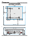
LINE LEVEL ANALOG AUDIO OUTPUTS :
The Bryston B100 integrated amplifier comes equipped with 2 pairs of gold plated analog RCA jacks for out-
puts: PREAMP OUT and RECORD OUT.
• PREAMP OUT is normally connected, internally, via the CONNECTED/SEPARATE switch, to POWER AMP IN
• RECORD OUT output is not affected by volume, balance or mute controls.
DIGITAL AUDIO INPUTS:
In the B100-DA model, which contains a stereo D/A converter module, there are 4 digital audio inputs avail-
able.
Two TOSLINK optical inputs are selected by pressing the D3 (TOSLINK-1) or D4 (TOSLINK-2) buttons on the
front panel (when in digital mode) or on the handheld remote.
Two SPDIF coaxial inputs can be connected to the B100-DA using the RCA input jacks labeled D1 and D2. To
select these inputs first place the unit in digital mode by pressing the DIGITAL4Select button on the front panel (or
the A/D button on the handheld remote) and then press the D1 or D2 button on the front panel or on the remote).
When the green LED above the font panel DIGITAL4SELECT switch button in ON concurrently with either the D1
(CD), D2 (TUNER), D3 (TV) or D4 (VIDEO) LEDs, then digital mode is engaged.
Note: Whatever digital input was previously selected in Digital Mode will be automatically reselected
upon re-entering Digital Mode (from Analog Mode). Similarly, when re-entering Analog Mode from
Digital Mode the previously selected analog input will be automatically re-selected.
See also the DIGITAL-to-ANALOG CONVERTER OPTION section for more information.
HEADPHONE JACK:
There is a quarter inch headphone output jack available on the front panel of the Bryston B100 integrated
amplifier. The headphone output is driven directly from the preamplifier section utilizing separate headphone
buffers. Inserting the headphone jack mutes the loudspeakers automatically (indicated by the mute LED on
the front panel turning red). The B100 PREAMP OUT is also muted.
You can adjust the volume setting of the headphones by using the volume control on the front of the B100 inte-
grated amplifier. You may also utilize the remote control unit to adjust headphone volume. The headphones
cannot be muted with the remote control unit or the front panel Mute. Only headphones with impedances of
greater than 50 ohms should be used.
AUXILIARY IR INPUT:
This mono 1/8” (3mm) phone jack allows a direct connection to equipment whose remote control system pro-
vides an output from their infra-red LED drive circuit. The signal connected to this jack, which is expected to
be a 5 volt logic level, should be ≥2.5Vdc and ≤10Vdc. The tip of the phone jack is positive (+) and the ring is
negative (-).
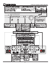
LED STATUS INDICATORS:
CLIPPING: This LED (light emitting diode) will flash RED when the output waveform is clipped thus
indicating an overload condition.
MUTE: Lights RED to indicate the outputs are muted..
POWER: GREEN indicates normal operation
RED indicates Standby
Blinking RED/GREEN a fault or thermal overload problem in the unit.