


6BSST THREE CHANNEL POWER AMPLIFIER
5
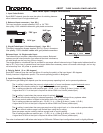
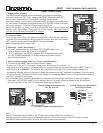
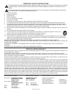
Power Control Panel
1. Master circuit - breaker.
The 6BSST uses a magnetic-trip circuit breaker (1) to protect the amplifier.
This switch should be ‘OFF’ when installing the 6BSST. When switched ‘OFF’
all A/C power is removed from the amplifier, including standby power.
The circuit breaker is not the day to day power switch and should be switched and
left ‘ON’ after the installation is complete.Use the ‘SST POWER” switch or an exter-
nal control voltage to Power-up or Power-down the amplifier.
Should the breaker trip, lower or remove the amplifier input signals. Switch the
breaker to the ‘ON’ position. Then power the unit up normally. The circuit breaker
must be ‘ON’ at all times for the 6BSST to operate.
2. AC power input.
This is a high current plug for the power cord receptacle. Check that the voltage rat-
ing at the right of the connector conforms with your locality. With the circuit breaker
‘OFF’ insert the power cord into the 6BSST, then plug the other
end to an approprate A/C power outlet.
3. Power-Up ( Local / Auto switch. )
A. In “Local” position either the front panel ‘SST POWER” switch or an
external voltage controls the power-up of the 6BSST.
B. “Auto” is used when the 6BSST is powered from a switched power outlet.
The ‘SST POWER’ switch and / or control voltage will function normally
after the initial power up.
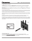
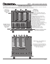
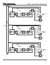
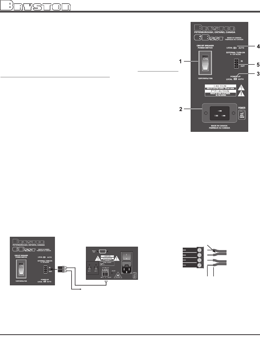
4. External control voltage power up ( Local / external switch.)
A. To power-up the 6BSST using an external control voltage,
Supply a 4v to 12v A/C or DC control voltage to the ‘IN’ terminals of connector ( 5 ).
Use paired wire of 22 gauge to 18 gauge sufficient in length between the source device and the 6BSST. (see ‘W’ )
Select switch (4) to “External”. The amplifier will now power-up only when the control voltage is present (on).
Immediately following power up, the control voltage will appear at the ’OUT’ terminals of connector (5) for the control
of other equipment.The Removal of the control voltage ( 0v) causes the 6BSST to turn ‘off’ and the control voltage at
the ‘OUT’ terminals is interrupted.
B. In the“Local” setting of switch (4) the 6BSST will ignore the control voltage, and power up only by using the
front panel ‘SST POWER’ switch, or as in section 3 above. If a control voltage is present at the ‘IN’ terminals it
will still be available at the ‘OUT’ terminals after the power-up sequence.
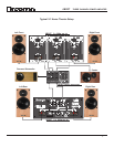
1/4”
strip
Control voltage wire preparation
for screw terminals
18 to 22
gage
wire
separate 1”
Control Voltage equipped source
4 to 12v ac or dc
Note:
The ‘OUT’ terminals are connected to the ‘IN’ terminals once the 6BSST has powered-up.
The control current is determined by the source equipment. The carrying current of the ‘OUT’ relay is 2 amps.
The 6BSST itself draws less than 2 ma from the control current when operating.
to other voltage controlled devices
fig W