


8
Divide this by 3 = 4.75 or 4 steps. This is the number of tap settings to lower the system by – so we will use 8W
taps. (Note that this system already has 2 dB of head room more than the 6” system.)
As this is a rule of thumb, you will need to test the SPL in the room to determine the proper tap setting. If you
want more head room on the amplifier, set the taps to 16W.
The last calculation you need to do is the total amp power required, taking into account transformer losses in the
system which equals 20% of available power. There are a total of 12 speakers @ 8 W each so you need:
12 x 8 x 1.2 = 115 watts of amplifier power
or 12 speakers @ 16W:
12 x 16 x 1.2 = 230 watts of amplifier power.
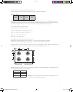
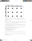
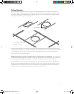
So for the room above we have a 60 ft x 40 ft x 12 ft high. = 28,800. This means you should use 2 subwoofers. If
you want extreme bass, use 4, but in most applications, you will want to use 2. Placing these in the room is easier
and provides more flexibility; remember to keep them at least 2 feet from any wall or corner. If you put them near
a corner you gain 6dB of output. As far as tap settings, use a similar calculation to the speakers.
The Max SPL at the listener location is 101 – (79.6 / 12) = 94.4 dB (this is more conservative than the speakers,
but allows for stronger bass in the room). If you want background levels in the room, then you will want to set the
taps to 8W each.
As you can see from these calculations using the Boston Acoustic Commercial Speaker Calculator will give you
these designs much easier. We encourage you to use it instead of doing the calculations by hand.
Speaker Wires
After the speaker installation locations have been chosen, you must run wires to the amplifier that drives them.
The electrical codes in your area may require the use of special wire that is resistant to exposure called “plenum
rated” wire. Check with an electrical safety inspector in
your area to see if such wiring is required.
One of the main advantages of high voltage CV systems is that relatively light gauge wire can be used, even over
long distances. In most installations 18 gauge wire will be more than enough. Only in very high power systems is
anything heavier needed.
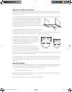
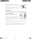
Speaker Connection Polarity
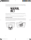
It is important that all the speakers in a system are hooked up with the same polarity or “in phase.” The PRi se-
ries models are supplied with a Molex plug-in connector to facilitate installation. Speaker wires are connected to
the plug-in connector then, just before installing the speaker, the Molex connector is plugged in.
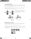
This illustration shows the connector on the speaker and the plug-in connector for the speaker wires. Note the
label beside the speaker connector. It shows the middle two pins on the connectors are “–” and “+”. The outer
two pins are labeled “LOOP +” and “LOOP –”. The “LOOP” connections are con
-
nected to the regular “+” and “–” connections inside the speaker and facilitate
connecting multi-speaker installations. Use the color coding or other marking on the
speaker wires to be sure that the “+” terminal of the amplifier is connected to the
“+” terminal of the speaker, and “–” is connected to “–”, at every connection.
*,Ê-«i>iÀ
iVÌÀ
*Õ}
iVÌÀ
142-002698-D OWNERS MANUAL PRICV8 8 10/4/07 3:24:08 PM