


10
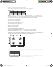
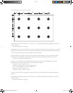
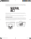
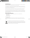
The second example shows the wires to the second speaker and all the following speakers connected to the
“loop” terminals. The “loop” terminals are connected to the regular “+” and “–” terminals inside the speaker.
This makes connecting the wires to the terminals easier. But it also means that if the one speaker is unplugged
for any reason the signal to the following speakers is cut off.
Parallel connections can also be made by connecting wires from all the speakers directly to the amplifier ter
-
minals, typically referred to as “home run” connections. This typically results in more wire being used – usually
something you want to avoid.
The information above only applies to 70V systems. If you use the Dir X setting of the switch on the front, bypass
-
ing the transformer, connect the speakers as you would any conventional low impedance speakers.
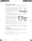
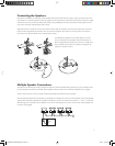
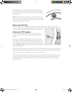
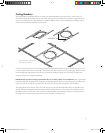
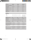
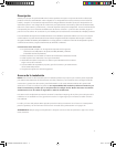
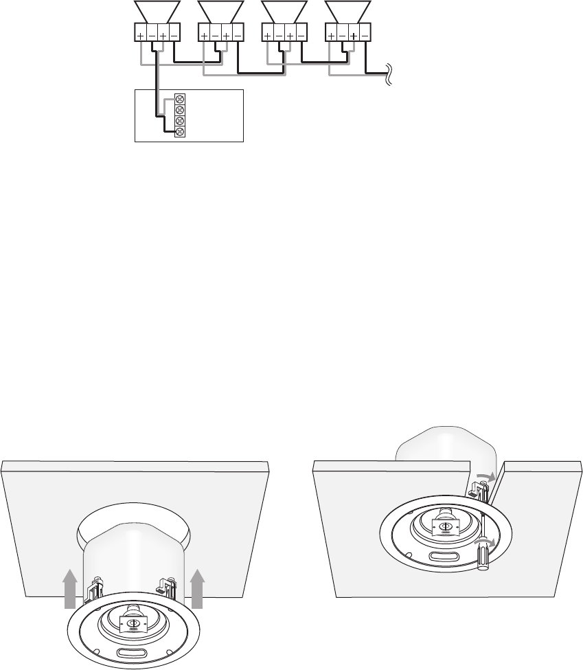
Installing the Speakers
Once the installation location has been prepared and the speaker has been connected, the installation of the
speaker is easy. Simply lift the speaker into the installation hole. Use a phillips screw driver to pivot the mounting
clamp arm outward and draw them down against the back of the mounting surface. Then gradually tighten the
mounting clamp screws, alternating among them, until the speaker is firmly clamped in place. Do not use exces
-
sive force when tightening the mounting clamp screws.
ÇäÊ6Ê>«wiÀ
Çä6
Óx6
{Ê"-
"
ÇäÊ6Ì
""* ""*
ÇäÊ6Ì
""* ""*
ÇäÊ6Ì
""* ""*
ÇäÊ6Ì
""* ""*
142-002698-D OWNERS MANUAL PRICV10 10 10/4/07 3:24:09 PM