


6
Venice_Intro.fm 1/07
I
NTRODUCTION
EnglishDeutschFrançais DanskEspañolItalianoSvenska Nederlands DanskItalianoSvenska DeutschNederlands EnglishFrançais Español
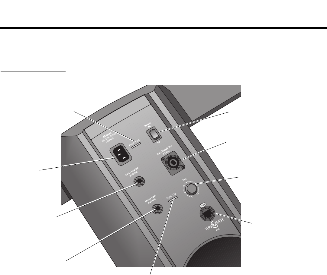
Connections and controls
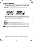
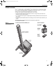
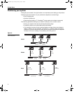
The top panel of the power stand provides system connectors and controls (Figure 2).
Figure 2
Power stand top panel
Power switch
Switches the system
on and off.
AC Mains
AC power input
connector.
Bass - Line Out
Post-DSP bass signal output.
Accepts a ¼" TRS phone cable.
Used to drive a PackLite
®
power
amplifier.
Bass Module Out
Bass output signal for driving one
or two B1 bass modules. Accepts
a 4-wire bass module cable.
Trim
Adjusts the level of the
analog input signal.
ToneMatch
TM
port
Digital audio and power con-
nection for the optional T1
ToneMatch audio engine.
Accepts the included
ToneMatch cable.
Analog Input
A line-level analog input. Accepts
a ¼" TRS phone cable. Used for
an instrument or other audio
source.
Signal/Clip LED
Indicates status of the analog input signal.
Green = normal input
Yellow = input approaching clipping
Red = input clipping
Power/Fault LED
Indicates power status.
Blue = system on
Red = system fault
Venice_Intro.fm Page 6 Friday, January 19, 2007 8:52 AM