


Operation
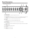
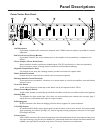
Front Panel Controls & Indicators
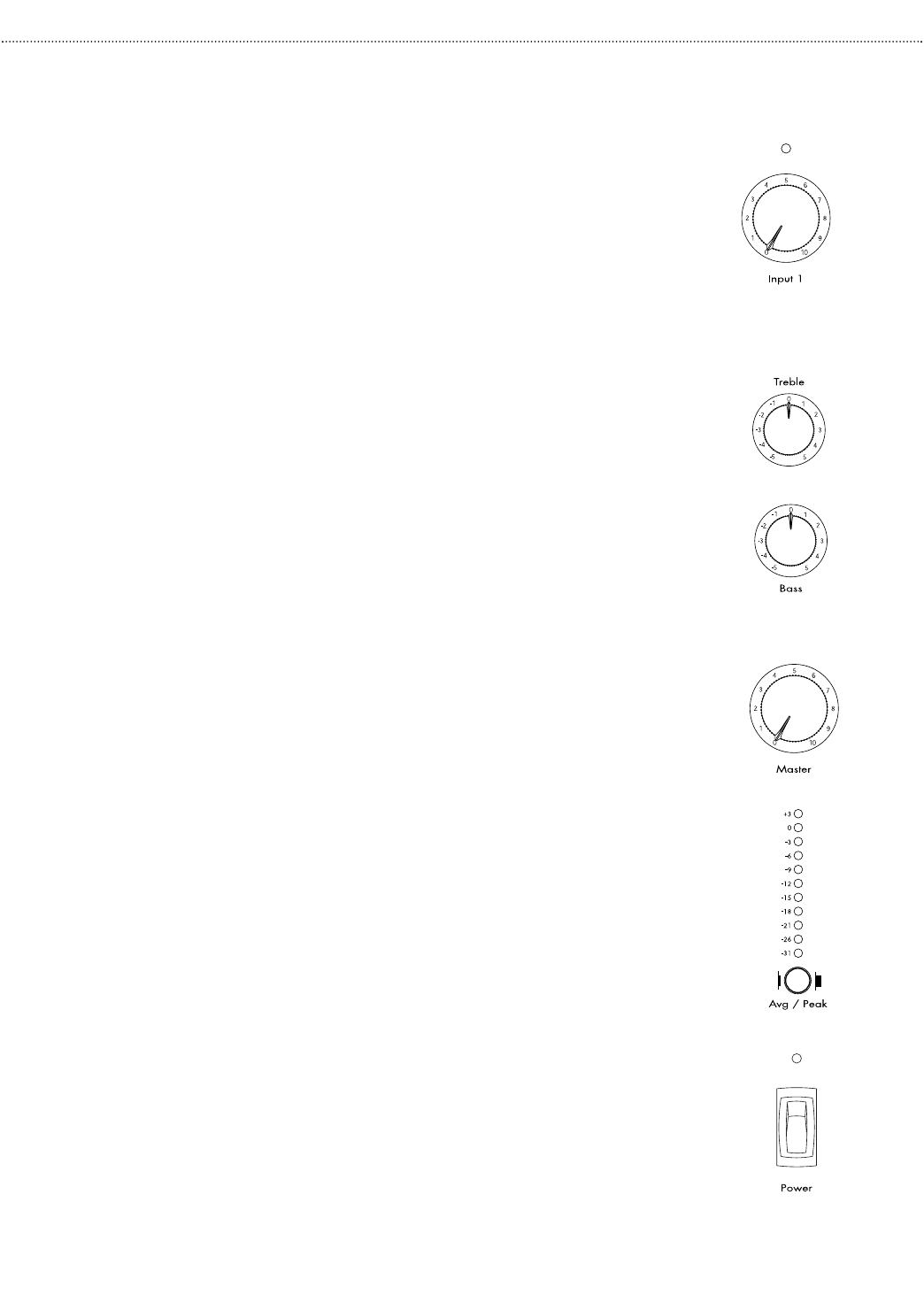
Input Volume Controls
Each input module may be individually controlled by its corresponding
volume control knob.
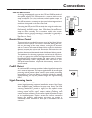
Signal / Clip Indicator
A single LED located above each channel’s volume control indicates the
audio activity of that channel’s input. Green indicates signal present at the
input. Red indicates that the input signal coming from the input module
into the amp is clipping and distorted.This is caused by either an input
signal that is too high or an input module volume control (gain) that is
set too high.
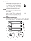
Bass and Treble Controls
The treble control has a cut/boost range of +/- 10 dB at frequencies
above 10 kHz and provides a roll off after 20 kHz to reduce gain above
the audio range.
The bass control has a cut/boost range of +/- 10 dB at frequencies below
100 Hz. When driving speakers using the direct-coupled output
terminals, the bass filter’s response is flat to 20 Hz. When driving
speakers using the transformer-coupled output terminals, the Power
Vector amplifier automatically changes the bass filter’s response to a
bandpass shape to reduce the level of bass frequencies below 40 Hz.This
filter shape helps to avoid overdriving the output transformer with low
frequency signals that may cause noticeable distortion due to magnetic
saturation of the transformer’s core.
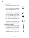
Master Volume Control
The overall volume level of the amplifier is set by a Master Volume
control.The Master Volume control is motorized and can be controlled
by manually adjusting the knob or by a remotely-mounted control
station. Connections and requirements for the remote control station
are described in the Connections section, under Remote Volume Control.
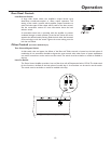
Average / Peak Switch & LED Output Meter
The LED Output Meter is an 11-segment meter that registers either the
average or the peak level of the amplifier’s output signal.A red indicator
is provided at the +3 dB level to indicate amplifier clipping. Amber
indictors at the 0 dB and -3 dB levels indicate high amplifier output
levels. The remaining 8 indicators (green) provide an indication of the
output signal’s dynamics.The meter can be set to read either the average
output signal level or the peak output signal levels by using the Average
/ Peak Switch at the bottom of the meter. In for average; out for peak.
Power Switch / Power Indicator
The AC power to the amplifier is controlled by the Power rocker switch.
A red LED indicator lights to confirm the power on status of the
amplifier.
9