


Installation
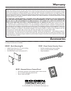
Package Contents
• Power Vector Amplifier • Module Covers (8)
• Switch Lock • 12 mm Module Cover Screws (16)
• Instruction Manual
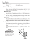
Ventilation and Mounting
Models V250 and V150
When rack or table mounting models V250 and V150, allow a minimum clearance of 1-1/4" on the left side of
the unit for proper ventilation of the fan exhaust and a minimum top and bottom clearance of 1/2". The right
side has no specific clearance requirement. These are minimum acceptable clearances, though the more space
provided on the left side, top, and bottom, the better.
Models V100,V60, and V35
When rack or table mounting models V100, V60, and V35, which are passively cooled, allow a minimum
clearance of
1
/2" for the bottom (set by the height of the unit’s feet) and a minimum of 1" from the top to other
obstructions. The sides have no specific clearance requirement. These are minimum acceptable clearances,
though the more space provided, both top and bottom, the better.
Rack Mounting
When stacking equipment in a rack, the amplifier should either be on the bottom of the stack or above
equipment that does not produce heat.This will ensure that cool air is available to the unit’s heat sinks.A rack
mount bracket kit (model RPK87)is available for the Power Vector series of amplifiers.
Shelf/Table Mounting
When using a shelf or table mount, the amplifier should stand alone with no equipment on top of it or below
it, especially for the V100,V60, and V35 models.If the amplifier must be stacked with other equipment,care must
be taken to ensure that all the minimum clearance distances are met and that the equipment below the
amplifier produces little significant heat. Rubber feet are installed on the amplifier to allow it to be placed on a
tabletop.
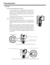
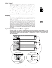
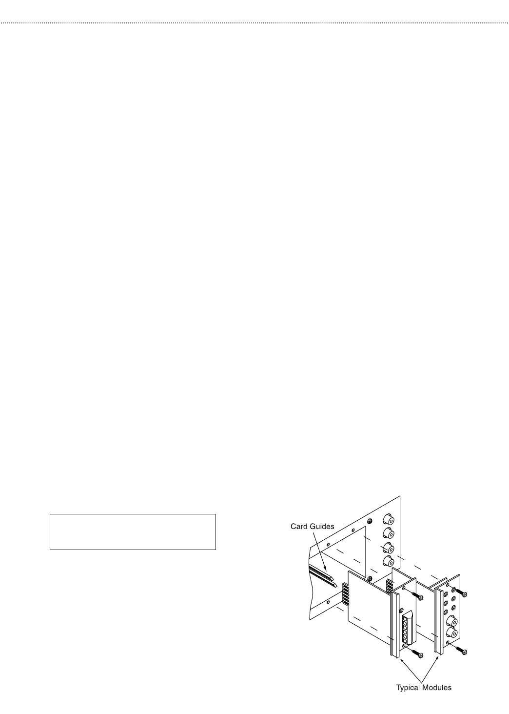
Module Installation
Eight module bays are available to accept Bogen’s new advanced input modules. Module bays 7 & 8 can also
accommodate Bogen’s new advanced output modules, thereby allowing users to customize the amplifier to suit
the needs of the installation. (The bays will not accept Bogen’s older style plug-in modules.)
Before installing a module, read the instructions included with the module and make the desired jumper setting
changes.
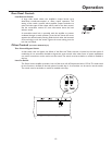
The modules are installed by simply sliding them along the card guides inside the module bays until the
faceplate firmly sits against the chassis, then use the two screws supplied with the module to secure it to the
chassis.
• Modules should slide in easily.
• Output modules will not fit in bays
1-6.
• Output modules can only be installed in bays 7 & 8.
• Output modules have 8 contacts on each side.
• Input modules have 6 contacts on each side.
• Older style Bogen input modules (4
1
/2" in length) are
not usable in the Power Vector amps.
- CAUTION -
DO NOT FORCE MODULES
4