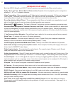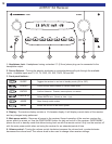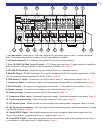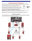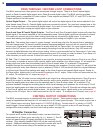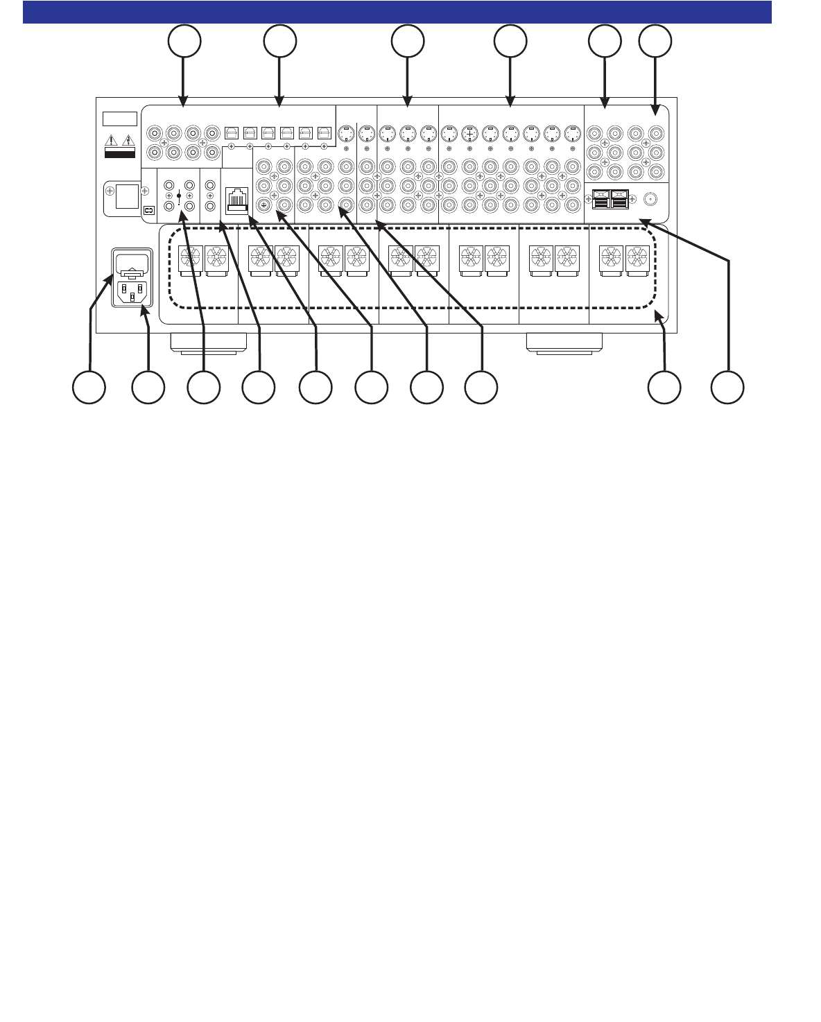
1. AC fuse holder - Holds the AC Line fuse. Replace only with same type and value - 12amp Slow Blow.
Note: The voltage rating label is located on the AC fuse holder cover plate.
2. AC input receptacle - For attaching the supplied AC power cord to the receiver.
3. Four 10-12VDC @ 50mA Control Outputs - 1/8" (3.5mm) mono mini plug. Trigger outputs for controlling
external devices, such as amplifiers, projection screens, IR emitter, etc. Page 18.
4. ZA & ZB IR Data Input - Accepts IR from an external IR source. Internally summed.
5. Main RJ-45 jack - RS-232 input/output for computer interface and RS-232 controller applications. A B &K
CK1.2 keypad can also be connected to the RJ-45 jack. Page 36.
6. DVD-Audio 5.1 inputs - Connections for a DVD-Audio or other 5.1 analog source device. Page 13.
7. Surround outputs - Variable level outputs for driving external power amplifiers or powered speakers. Page 17.
8. Zone B Output - Line outputs for supplying the second zone. Configurable fixed or variable. Page 19.
9. Speaker outputs - Connections for speakers in the main theater zone. Page 15.
10. Antenna inputs - Connections for the AM and FM antennas. Page 21.
11. Component Video output - Component video pass through. Transcoded component video output. Page 14.
12. Component Video inputs - Three assignable component video inputs. Page 14.
13. A/V Source inputs - Seven sources can be connected using analog audio, composite video or S-Video.
14. A/V Source record outputs - Tape loop outputs will provide analog audio / video source signals for Zone
A or Zone B recording. Page 18.
15. Optical SPDIF Digital - Optical digital connections for connecting optical digital audio signals from the
source to the receiver. 5 optical digital inputs, 1 digital output. Page 13.
16. Coax SPDIF Digital - Coax digital inputs are used to connect coax digital audio signals from the source
to the receiver. 6 coax digital inputs, 2 digital outputs. Page 13.
11
Audio/Video Systems Hand-Made in the U.S.A.
FRONTSURRND
SUB CENTER
+
EXPANSION
SERIAL #
AC LINE
IN 1 IN 2 IN 3V1V2TVDVDCDSATTAPETAPE
V1
ZB/V2
DVD
INPUT
A/V SOURCE OUTPUTS A/V SOURCE INPUTS COMPONENT VIDEO
www.bkcomp.com
AM FM
ANTENNA
ZONE A ZONE B
OUTPUTS
ZONE BFRONTSURRND S BACK
CENTERSUB
SURROUND OUTPUTS
OPTICAL S/PDIF DIGITALCOAX S/PDIF DIGITAL
OUT SAT CD DVD V2 V1
V1V2TVZAOUT
ZB OUT SAT CD DVD
CONTROL OUT IRINPUT
ZONE A
IEEE
1394
12VDC
50 mA
21
34
POSITIVE
NEGATIVE
POSITIVE
NEGATIVE
POSITIVE
NEGATIVE
POSITIVE
NEGATIVE
POSITIVE
NEGATIVE
POSITIVE
NEGATIVE
POSITIVE
NEGATIVE
SURROUND LEFT FRONT LEFTCENTER FRONT RIGHTSURROUND RIGHT SURROUND BACK RIGHTSURROUND BACK LEFT
BK&
SB
IMPLY ETTER!
FUSE
CAUTION: FOR CONTINUED
PROTECTION AGAINST RISK
OF FIRE REPLACE ONLY WITH
SAMETYPEANDVALUEFUSE
OUTPUT
IR INPUT
ZONE B
AUDIO
RS-232
PORT
CAUTION
RISK OF ELECTRIC
SHOCK DO NOT OPEN
5
678
4
21
910
1112
13
14
1516
3


