


6
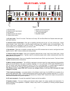
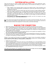
INPUT CONNECTIONS
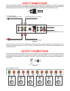
Each pair of amplifier channels have their own ‘Local’ input and output RCA connectors. The inputs are designed
to accept line level audio from a preamplifiers unbalanced output connectors. Output expansion is accommodated
with the supplied output connectors. These outputs are effectively a direct pass through from the inputs.
RCA connector
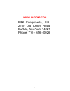
Typical input setup:
1/2OUT
CTRL 1/2
1IN
OUTIN
2
IN
OUT
MASTER
CONTROL
OUT
IN
BUS
OUT
IN
IN
1234
ON
MIN MAX
AMP ON
L+R
SENSE
BUS
1234
ON
LEVEL
OUT
L
L
R
R
L
L
R
R
FROM PREAMPLIFIER A's LEFT OUTPUT
FROM PREAMPLIFIER B's LEFT OUTPUT
FROM PREAMPLIFIER A's RIGHT OUTPUT
FROM PREAMPLIFIER B's RIGHT OUTPUT
TO 2ND AMPLIFIERS LEFT INPUT
TO 2ND AMPLIFIERS RIGHT INPUT
Figure 3
Figure 3 shows ‘Local’ OUT 1 and 2 connections and how they may be used to connect to another amplifier. OUT
1 source is the same signal as IN 1. OUT 2 source is the same signal as IN 2. BUS inputs are buffered and sent
to the BUS outputs.
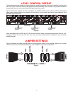
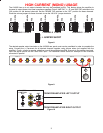
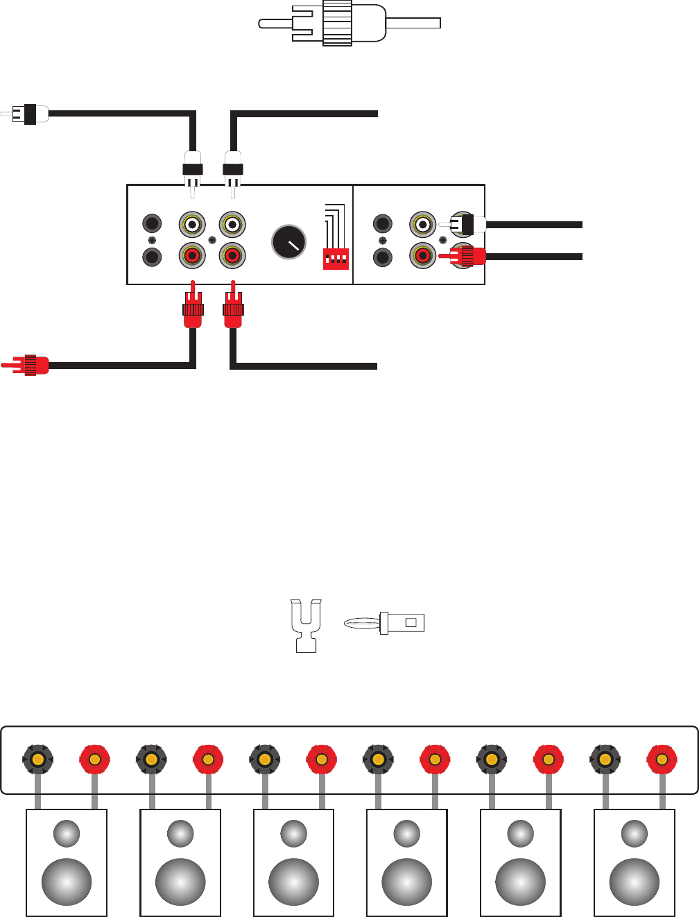
OUTPUT CONNECTIONS
Five way binding posts are provided. One pair for each channel. They are designed to accept a banana-type plug
or spade lug connector (shown below) and are color coded for easy identification. The red (+) post should always
be connected to the speakers (+) connection. The black (-) post should always be connected to the speakers (-)
connection.
Spade Connector
Banana Jack
Figure 4
Typical amplifier hookup:
(+)
(-)
SPEAKER
(+)
(-)
SPEAKER
(+)
(-)
SPEAKER
(+)
(-)
SPEAKER
(+)
(-)
SPEAKER
(+)
(-)
SPEAKER
OUT 6
PLUS PLUS PLUS PLUS PLUSMINUS MINUS MINUS MINUS MINUS
OUT 5 OUT 4 OUT 3 OUT 2 OUT 1
PLUS MINUS
Figure 5