


7
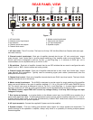
LEVEL CONTROL DEFEAT
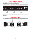
The following procedures should only be performed by a qualified technician. Each pair of amplifier channels have
their own ‘Local’ level control that may be bypassed to allow paralleling output channels. The jumper modules are
located inside the unit, on the circuit board, just behind the level controls.
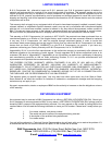
Figure 6 shows how jumpers are used to configure the AV2600 amplifier (level controls enabled). Rearranging
these jumpers allows configuring the amplifier for use without a level control (required for proper operation using
paralleled output channels).
P/N 12926 Rev AP/N 12926 Rev A
B&K Components Ltd.B&K Components Ltd.
GNDR
-5+5
+5GND GND
GND
-5+5
R24
U9
U4
U2
R45
R43
R38R36
R42R40
R44R44
R3
R26
R23
JP3
D5
D3
CON4 CON3 CON2
+
C29
C10
C9C7
C8
C6
C5
C4
C3
C2
+
C28
CON5
C11
R28
U10
U6U5
R4
R30
R27
JP2
D9
D7
+
C31
C16
C15C13
C14
C12
+
C30
C17
R32
U11
U8U7
R5
R34
JP1
D13
D11
+
C33
C22
C21C19
C20
C18
+
C32
C23
+
C1
+
C24
+
C25
+
C26
+
C27
D1
D2
R1
R2
R7
R19
R22
R68
R8 R21R9 R20
U1
C38C39
R109
R110
R111
R112
R114
R115
R31
C36C37
R100
R101
R102
R103
R105
R106
C34
C35C35
R52
R58
R59
R65
R97
R96
U3
CON12
BACKPANEL
CHANNELS 1 AND 2
VOL AND NO VOL
JUMPERS
CHANNELS 3 AND 4
VOL AND NO VOL
JUMPERS
CHANNELS 5 AND 6
VOL AND NO VOL
JUMPERS
Figure 6.
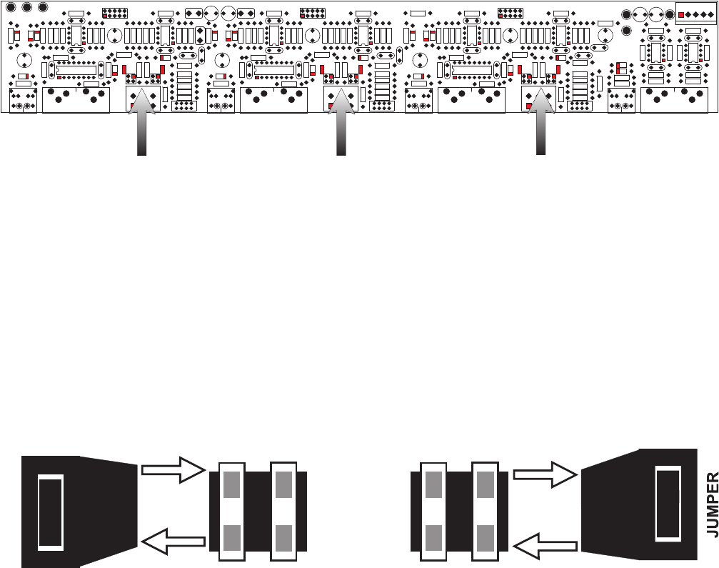
When reconfiguring the AV2600 to NOT USE the level control, simply move the desired jumper from the ‘VOL’
(default) and place it across the ‘NO VOL’ pins.
Note: the level control should be disabled for each paralleled
amplifier channel.
JUMPER SETTINGS
Figure 6 illustrates the jumper modules used in configuring each channel. Each amplifier channel has a jumper
terminal location that is conveniently labeled for easy verification of its current configuration.
JUMPER
VOL
NO VOL
NO VOL
VOL
CHANNELS 1 AND 2
Figure 7