


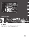
10 11X-TOUCH Quick Start Guide
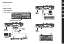
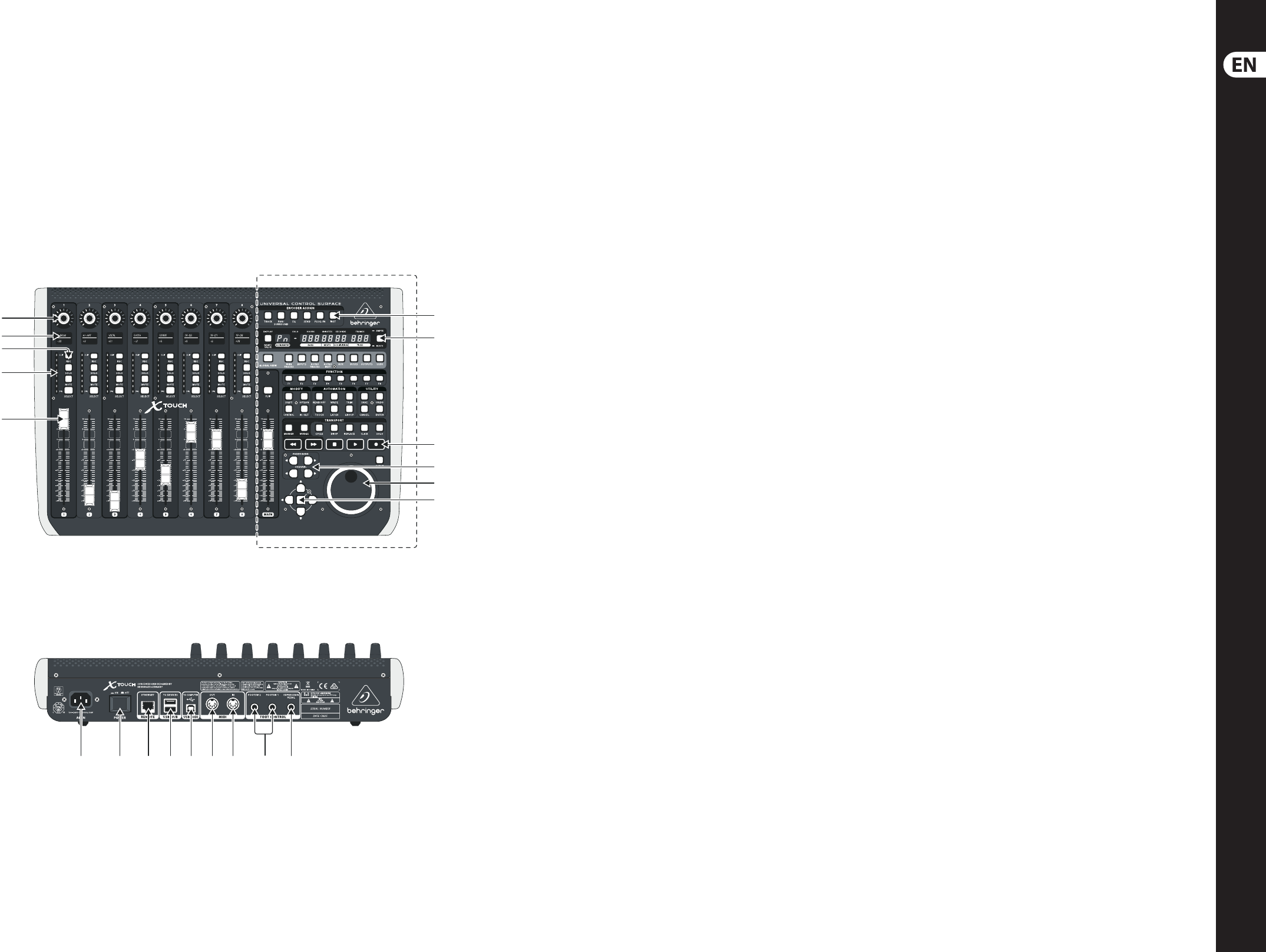
X-TOUCH Controls
(EN) Step 2: Controls
Operation Modes
The X-TOUCH supports HUI and MC
communication protocols for seamless
integration with every compatible music
production software. Other modes will
be made available with future rmware
updates. The procedure for changing modes
is shown in the Getting Started section.
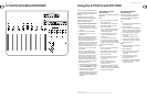
(1) Push encoder knobs – these 8 endless
encoders each have a detent and push
function (not illuminated), and a 13-segment
amber LED ring. These are typically used
in Digital Audio Workstation (DAW)
applications for ne control of parameters
such as aux send and pan control of channels
1 to 8. Use the encoder assign buttons
in the master section to select what the
encoders control.
(2) Scribble strips – these 8 LCD displays
indicate various parameters and labels
as shown in the DAW software. They are
also used to view various settings and
adjustments of the unit that can then be
adjusted with the encoders.
(3) Channel buttons – these 4 buttons per
channel are used for individual DAW mixer
channel applications:
Rec – arms the channel for recording.
Solo – isolates a channel in the mix. The solo
LED in the display will light when one or
more channels are soloed in the mix.
Mute – mutes the channel.
Select – this selects the channel for editing.
The mixer controls are then dedicated to
setting up the selected channel, with details
shown in each scribble strip.
(4) Channel meters – these 8-LED meters
show the signal level of each channel, and
indicate when a signal is present, and when
it is clipping.
(5) Faders – these touch-sensitive motorized
100 mm faders are typically used for
ne control of level functions in DAW
applications. There are 8 channel faders and
1 master on the right. The FLIP button above
the master fader switches between encoder
control and fader control, where ner control
of parameters is needed.
Master Section
The exact function of the buttons will
vary widely from one DAW to the next.
We recommend that you read your DAW’s
documentation regarding how it operates
with external control surfaces. Among other
things, there are buttons that take the
place of keyboard shortcuts, utilities, and
automation. The following details show
some of the more common features of
this section:
(6) Encoder Assign – these 6 buttons are
used to select the function of the encoders.
Their exact function will vary between
DAWs, but may include track level, pan, EQ,
aux send, insert e ects plug-ins, and so on.
(7) Display – the display can be switched
between SMPTE timecode of hours,
minutes, seconds and frames, or BBT bars,
beats, and ticks. LEDs show the selection of
SMPTE or Beats.
(8) Transport buttons – the ve lower
buttons have familiar markings used for DAW
transport applications (rewind, fast forward,
stop, play, record).
(9) Fader Bank and Channel – the left or right
bank buttons move the channels up and
down by 8 channels at a time. The channel
buttons move the channels up and down in
single steps.
(10) Jog/Shuttle – the wheel is used for editing
the audio in the DAW. Press the SCRUB
button to switch the wheel between Jog
and Shuttle.
(11) Navigation buttons – these allow you to
navigate up/down and left/right, and zoom
within the DAW screen.
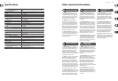
Rear Panel
(12) AC IN – securely connect the supplied AC
power cord here. Connect the other end of
the cord to your local AC mains supply. Do not
defeat the safety ground.
(13) Power switch – press in to turn on the unit,
press out to turn it o . Do not turn it on until
all connections have been made.
(14) REMOTE – this port is an Ethernet interface
for connection to a DAW supporting RTP
MIDI, or remote controlling BEHRINGER
digital mixer series (future implementation).
(15) USB HUB – these 2 USB type A connectors
are used for connecting external USB
hardware such as a USB mouse, a keyboard,
USB MIDI controllers such as the X-TOUCH
MINI, and USB MIDI keyboards. The Hub
communicates directly to the computer
and not to the X-TOUCH. Each connector
can supply 5V USB power. The hub is only
active when the X-TOUCH is powered on, and
connected to a live computer via the USB
MIDI connector.
(16) USB MIDI – this USB type B connector is
used to connect to a computer’s USB port for
MIDI data transfer (send/receive), and USB
Hub communications.
(17) MIDI OUT – this 5-pin DIN connector
sends MIDI data to the MIDI IN of external
MIDI devices.
(18) MIDI IN – this 5-pin DIN connector receives
MIDI data from the MIDI OUT of external
MIDI devices.
(19) Foot Control Foot Switch 1 and 2 – these
¼ " connectors are used for standard sustain
pedals for momentary or toggle MIDI
data control.
(20) Foot Control Expression Pedal – this
¼ " connector is used for a standard swell
pedal for continuous MIDI data control.
(12) (13) (14) (15) (16) (17) (18) (20)(19)
(1)
(6)
(7)
(8)
(10)
(9)
(11)
(2)
(5)
(4)
(3)
Master Section