


VIRTUBE VT30FX/VT15FX/VT15CD
Control elements 5
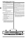
Front panel2.1
The {1} INPUT socket is the 1/4" connector for your guitar.
Please use a standard 1/4" TS connector.
CLEAN channel2.1.1
The {2} CLEAN CHANNEL LED lights up when the channel
is active.
The {3} VOLUME control determines the volume of the CLEAN
channel.
The {4} BASS control in the EQ section allows you to raise or
lower the bass frequencies on the CLEAN channel (VT30FX
only).
The {5} TREBLE control adjusts the treble frequencies on the
CLEAN channel (VT30FX only).
Press the {6} CHANNEL button to switch between the CLEAN
and OVERDRIVE channels. The channel LED lights up when
the channel is activated. With all models you can also switch
between channels using the footswitch provided.
OVERDRIVE channel2.1.2
The {7} OVERDRIVE CHANNEL LED lights up when the chan-
nel is active.
The {8} GAIN control determines the amount of gain applied
and hence the degree of distortion in the OVERDRIVE
channel.
The {9} BASS control in the EQ section allows you to raise or
lower the bass frequencies.
Use the [10] CONTOUR control (VT15FX / VT15CD: MID) for
additional, highly characteristic adjustment of the midrange,
so as to easily create traditional as well as ultra-modern
guitar sounds.
The [11] TREBLE control adjusts the treble frequencies.
On the VT30FX, the controls + {9}, (10) and (11) are effec-
tive on the OVERDRIVE channel only, since this amplier
has a dedicated equalizer for the CLEAN channel (see
also {4} and {5}).
The [12] VOLUME control adjusts the volume level of the OVER-
DRIVE channel.
FX section (VT30FX and VT15FX only)2.1.3
The [13] FX LED lights up when the effects processor is active.
Use the [14] FX PRESET control to select one of 16 effects.
Preset FX
1 - 4 Reverb
5 - 8 Delay
9 - 12 Chorus
13 - 16 Flanger
EffectsTab. 2.1:
The [15] FX LEVEL control adjusts the mix ratio between the
original and the effect signal.
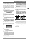
Connectors and POWER switch2.1.4
The [16] VTC push button activates and deactivates the VTC
Virtual Tube Circuitry.
The [17] CD IN connector allows you to connect the output signal
of a CD player, tape deck, or CD/MD walkman. For example,
you can play back music CDs or CDs accompanying a guitar
tutor while practising. This connector can also be used as
a LINE OUT output. In this case, the guitar signal is output
with no speaker simulation applied and can be routed to an
external amp or mixing console. This will not mute the built-in
loudspeaker of the VIRTUBE.
The [18] LINE OUT/PHONES jack is for headphones connection.
Internal speaker simulation is applied to the headphones
signal in order to produce an authentic signal. The built-in
loudspeaker of the VIRTUBE is muted when this connector
is used.
The headphones output signal can also be routed to a +
mixing console or other sound reinforcement system. To
do so, connect the headphones output with the line input
on the mixing console. Use a standard cable with 1/4" TS
connectors. If hum problems occur, you could insert a
DI box, e.g. BEHRINGER ULTRA-DI DI100 or DI120.
With too high a volume level some headphones tend to +
produce distortion. Please turn down the volume a bit,
until distortion stops.
Use the [19] FOOTSWITCH jack to connect the 1/4" TRS plug of
the footswitch supplied with the unit. The footswitch performs
a dual function: it switches between the two channels and
turns the FX on and off (VT30FX only).
The [20] POWER switch turns your VIRTUBE on and off. It
should always be in the OFF position when connecting the
unit to the mains.
Please note: Merely switching the unit off does not +
mean that it is fully disconnected from the mains. To
disconnect the unit from the mains, pull out the mains
connector. Before installation, please make sure that
the mains connector has not been damaged. If you do
not use the unit for an extended period of time, please
disconnect it at the mains.
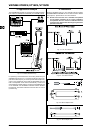
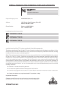
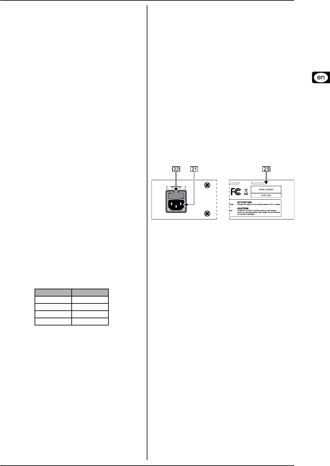
Rear panel2.2
VIRTUBE control elements (rear panel)Fig. 2.2:
The VIRTUBE is connected to the mains using a standard [21]
IEC receptacle. A suitable power cord is included with the
unit.
FUSE HOLDER/VOLTAGE SELECTOR[22] . Before connecting
the unit to the mains, ensure that the voltage setting matches
your local voltage. Blown fuses must be replaced with a fuse
of the same type and rating. On some units, the fuse holder
can be switched to one of two positions, i.e. 230 V and
120 V. Please note: when operating the unit outside Europe
at 120 V, a higher fuse rating is required (see Chapter 4,
“Installation”).
SERIAL NUMBER[23] .