


7
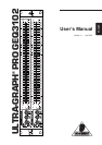
ULTRA-GRAPH PRO GEQ3102
You will find additional information in chapter 4 INSTALLATION.
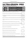
1.3 Control elements
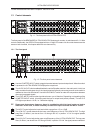
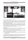
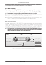
Fig. 1.1: The front panel of the ULTRA-GRAPH PRO
The front panel of the BEHRINGER ULTRA-GRAPH PRO features six controls, six switches and 2 x 31 slide
controls. Additionally, the GEQ3102 is equipped with two 12-digit LED meters. As all control elements are the
same on both channels, this chapter deals with one channel only.
1.3.1 The front panel
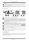
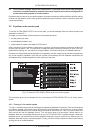
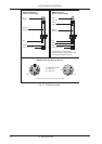
Fig. 1.2: The front panel control elements
1
Use the I/O METER IN/OUT switch to toggle the meter between input and output level. When the switch
is pressed, the ULTRA-GRAPH PRO displays the output level.
2
The AUDIO IN/OUT switch enables/disables the entire Equalizer section in the audio path. As this is a
relay-controlled hard-bypass circuit, the inputs/outputs are directly connected as soon as the switch is
released or the unit is switched off. Use the AUDIO IN/OUT switch to make A/B comparisons between
direct and processed signals.
3
The LEVEL METER monitors the signal level to warn you of distortion. Depending on the setting of the
I/O METER IN/OUT switch, this meter reads the input or output level (switch pressed). The red CLIP
LED lights up at about +18 dB, i.e. 3 dB below clipping.
+ Please note that extreme frequency boost in combination with high input levels can lead to
distortion. In this case, it will be necessary to reduce the input level with the INPUT control.
4
The INPUT control adjusts the input level within a range from -15 to +15 dB.
5
The LOW CUT control determines the lower cutoff frequency of the ULTRA-GRAPH PRO. The high
pass filter (18 dB/oct.) can be set from 10 through 400 Hz, in position 10 Hz the signal passes
unaffected.
6
The HIGH CUT control adjusts the upper cutoff frequency of the ULTRA-GRAPH PRO. The low pass
filter (18 dB/oct.) can be set from 2.5 through 30 kHz, in position 30 kHz the signal passes unaffected.
1. INTRODUCTION