


7
EURORACK UB1622FX-PRO/UB1832FX-PRO/UB2222FX-PRO/UB2442FX-PRO
SOLO
The SOLO switch is used to route the channel signal to the
solo bus (Solo In Place) or to the PFL bus (Pre Fader Listen). This
enables you to listen to a channel signal without affecting the
main output signal. The signal you hear is taken either before the
pan control (PFL, mono) or after the pan and channel fader
(Solo, stereo) (cf. chap. 2.3.10 Level meters and monitoring).
SUB (1-2 and 3-4)
The SUB switch routes the signal to the corresponding
subgroups. The UB2442FX-PRO has 4 subgroups (1-2 and 3-4).
MAIN
The MAIN switch routes the signal to the main mix bus.
The channel fader determines the channels volume in the
main mix (or submix).
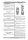
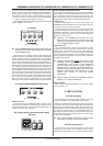
2.2 Stereo channels
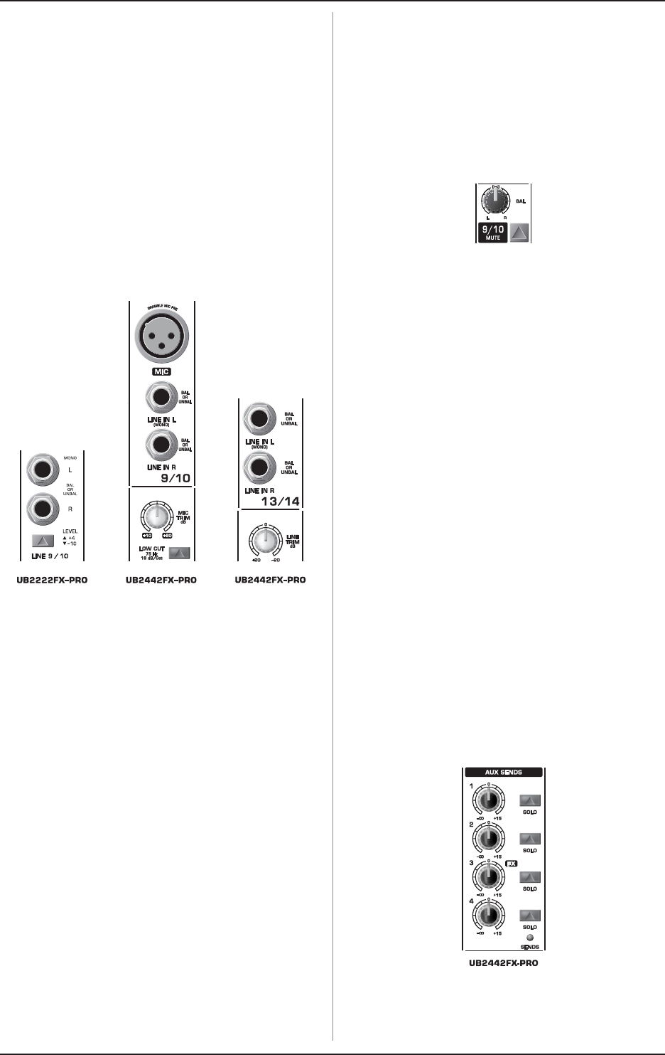
2.2.1 Channel inputs
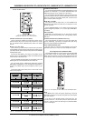
Fig. 2.5: The various stereo channel inputs
Each stereo channel has two balanced line level inputs on
jacks for left and right channels. Channels 9/10 and 11/12 on the
UB2442FX-PRO feature an additional XLR microphone jack with
phantom power. If only the left jack (marked L) is used, the
channel operates in mono. The stereo channels are designed to
handle typical line level signals, and, depending on model, have
a level switch (+4 dBu or -10 dBV) and/or a line TRIM control.
Both jack inputs will also accept unbalanced connectors.
LOW CUT and MIC TRIM
These two control elements operate on the XLR connectors of
the UB2442FX-PRO, and are used to filter out frequencies below
75 Hz (LOW CUT) and to adjust microphone levels (MIC TRIM).
LINE TRIM
Use this control to adjust the line signal levels on channels
13-16 (UB2442FX-PRO only).
LEVEL
For level matching, the stereo inputs on the UB1622FX-PRO,
UB1832FX-PRO and UB2222FX-PRO have a LEVEL switch to
select between +4dBu and -10dBV. At -10dBV (homerecording
level), the input is more sensitive than at +4dBu (studio level).
2.2.2 Equalizer stereo channels
The stereo channels contain a stereo EQ section. The cut-off
frequencies of the high and low bands are 12 kHz and 80 Hz
respectively, while the center frequencies of the high-mid and
low-mid bands are 3 kHz and 500 Hz respectively. The HIGH and
LOW controls have the same characteristics as the EQ in the
mono channels. Both mid range bands are of the peak filter type.
A stereo EQ is superior to two mono EQs on a stereo signal as
two separate EQs will usually result in a discrepancy between
left and right channels.
2.2.3 Aux sends stereo channels
In principle, the aux sends of the stereo channels function the
same way as those of the mono channels. As the aux sends are
mono, the send from a stereo channel is first summed to mono
before it reaches the aux bus.
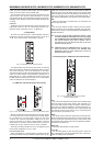
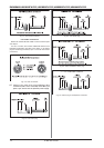
2.2.4 Routing switch, solo and channel fader
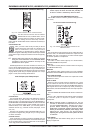
Fig. 2.6: Balance control and mute switch
BAL
The BAL(ANCE) control has a similar function to the PAN control
in the mono channels.
The balance control determines the levels of the left and right
input signals relative to each other before both signals are routed
to the left/right main mix bus (or odd/even subgroup).
The remaining control elements in the stereo channels perform
the same functions as their counterparts in the mono channels
(MUTE switch, MUTE and CLIP LEDs, SOLO switch, SUB and
MAIN switches and channel fader).
2.3 Interface panel and main section
Where it was useful to trace the signal flow from top to bottom
in order to gain an understanding of the channel strips, we now
look at the mixing console from left to right. The signals are, so to
speak, collected from the same point on each of the channel
strips and then routed to the main section all together.
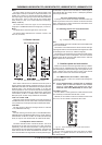
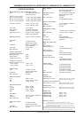
2.3.1 MON control, aux sends 1, 2 and 3 (FX)
Turning up the AUX 1 control in a channel routes the signal to
the aux send bus 1.
+ As the UB1832FX-PRO is equipped with an additional
monitor path, its first aux control in the channel
strips is named MON. The console also has a
dedicated master fader (MON SEND) for this aux path.
AUX SEND 1, 2 and 4
The AUX SEND 1 control governs the master send level of the
mix created by the individual channel AUX 1 sends.
Likewise, the AUX SEND 2 contol is the master control for the
aux 2 bus, and AUX SEND 4 controls the AUX 4 bus.
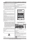
Fig. 2.7: The AUX SEND controls of the main section!
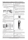
AUX SEND 3 (FX)
The FX control determines the signal level for effects
processing, i.e. regulates the level to an external (or the inter-
nal) effects device.
2. CONTROL ELEMENTS AND CONNECTORS