


5
EURORACK UB1622FX-PRO/UB1832FX-PRO/UB2222FX-PRO/UB2442FX-PRO
you need to know more about specific issues, please visit our
website at http://www.behringer.com. Additional information and
explanations about various music industry/audio technology
terminology can be found on individual product pages as well as
in the glossary.
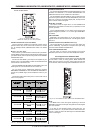
+ The block diagram supplied with the mixing console
gives you an overview of the connections between
the inputs and outputs, as well as the associated
switches and controls.
For the moment, just try and trace the signal path from the
microphone input to the aux send 1 connector. Dont be put off
by the huge range of possibilities; its easier than you think! If you
look at the overview of the controls at the same time, youll be
able to quickly familiarize yourself with your mixing console and
youll soon be making the most of all its many possibilities.
1.3 Before you get started
1.3.1 Shipment
Your mixing console was carefully packed in the factory to
guarantee safe transport. Nevertheless, we recommend that
you carefully examine the packaging and its contents for any
signs of physical damage, which may have occurred during
transit.
+ If the unit is damaged, please do NOT return it to us,
but notify your dealer and the shipping company
immediately, otherwise claims for damage or
replacement may not be granted.
1.3.2 Initial operation
Be sure that there is enough space around the unit for cooling
purposes and to avoid over-heating please do not place your
mixing console on high-temperature devices such as radiators
or power amps. The console is connected to the mains via the
supplied cable. The console meets the required safety standards.
Blown fuses must only be replaced by fuses of the same type
and rating.
+ Please note that all units must be properly
grounded. For your own safety, you should never
remove any ground connectors from electrical
devices or power cables, or render them in-
operative.
+ Please ensure that only qualified people install and
operate the mixing console. During installation and
operation, the user must have sufficient electrical
contact to earth, otherwise electrostatic discharges
might affect the operation of the unit.
1.3.3 Warranty
Please take time to fill out and return the warranty card within
14 days after the date of purchase, so as to be entitled to benefit
from our extended warranty. Alternatively, you can use our
online registration option available on the world wide web
(www.behringer.com). You will find the serial number on the
rear of your mixing console.
2. CONTROL ELEMENTS AND
CONNECTORS
This chapter describes the various control elements of your
mixing console. All controls, switches and connectors will be
discussed in detail.
2.1 Mono channels
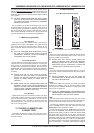
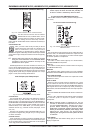
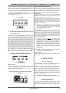
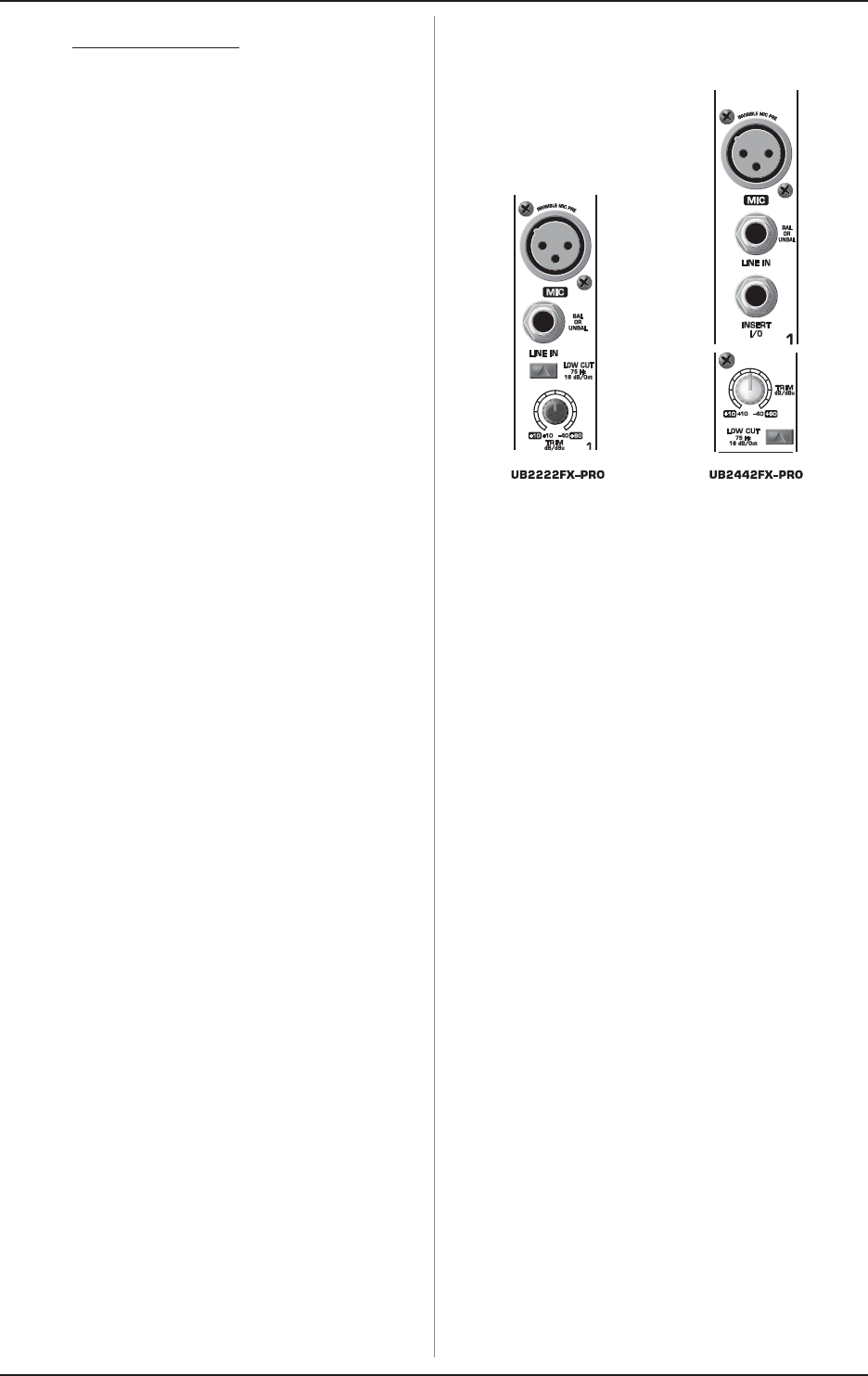
2.1.1 Microphone and line inputs
Fig. 2.1: Connectors and controls of mic/line inputs
MIC
Each mono input channel offers a balanced microphone input
via XLR as well as switchable phantom power (+48 volt) for
powering condenser microphones.
+ Please mute your monitor system before you
switch on phantom power. Otherwise potentially
damaging thumps will be sent to your speakers.
Please also note the instructions in chapter 5.5
Voltage supply, phantom power and fuse.
LINE IN
Each mono input also has a balanced line input on a 1/4" jack.
You can also connect unbalanced devices using mono jacks to
these inputs.
+ Please remember that you can use either the
microphone input or the line input of a channel, but
not both at the same time!
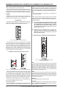
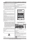
INSERT
Insert points enable the processing of a signal with dynamic
processors or equalizers. They are sourced pre-fader, pre-EQ
and pre-aux send. Detailed information on using insert points
can be found in chapter 5.3.
+ Unlike the UB2442FX-PRO, the UB1622FX-PRO,
UB1832FX-PRO and UB2222FX-PRO have their insert
points located on the rear of the console.
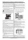
TRIM
Use the TRIM control to adjust the input gain. This control
should always be turned fully counter-clockwise whenever you
connect or disconnect a signal source to one of the inputs.
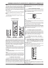
The scale has 2 different value ranges: the first value range
(+10 to +60 dB) refers to the MIC input and shows the
amplification for the signals fed in there.
The second value range (+10 to -40 dB) refers to the line input
and shows its sensitivity. The settings for equipment with st
andard line-level signals (-10 dBV or +4 dBu) look like this: While
the TRIM control is turned all the way down, connect your
equipment. Set the TRIM control to the external devices standard
output level. If that unit has an output signal level display, it should
show 0 dB during signal peaks. For +4dBu, turn up TRIM slightly,
for -10 dBV a bit more. Fine-tuning of a signal being fed in is done
using the level meter. To route the channel signal to the level
2. CONTROL ELEMENTS AND CONNECTORS